Expandable medical device with beneficial agent delivery mechanism

a medical device and beneficial agent technology, applied in the field of tissue-supporting medical devices, can solve the problems of difficulty in accurately placing stents or finding and retrieving stents that subsequently become dislodged and lost in the circulatory system, struts are frequently unstable, and display a tendency to buckle, so as to improve crush strength, improve resistance to compressive forces, and minimize elastic recovery

Inactive Publication Date: 2005-09-15
INNOVATIONAL HLDG LLC
View PDF11 Cites 10 Cited by
  • Summary
  • Abstract
  • Description
  • Claims
  • Application Information

AI Technical Summary

Benefits of technology

[0023] The present invention addresses several important problems in expandable medical device design including: high expansion force requirements; lack of radio-opacity in thin-walled stents; buckling and twisting of stent features during expansion; poor crimping properties; and excessive elastic recovery (“recoil”) after implantation. The invention also provides benefits of improved resistance to compressive forces after expansion, control of the level of plastic strain, and low axial shortening during expansion. Some embodiments of the invention also provide improved uniformity of expansion by limiting a maximum geometric deflection between struts. The invention may also incorporate sites for the inclusion of beneficial agent delivery.

Problems solved by technology

However, materials this thin are not visible on conventional fluoroscopic and x-ray equipment and it is therefore difficult to place the stents accurately or to find and retrieve stents that subsequently become dislodged and lost in the circulatory system.
When expanded, these struts are frequently unstable, that is, they display a tendency to buckle, with individual struts twisting out of plane.
Excessive protrusion of these twisted struts into the bloodstream has been observed to increase turbulence, and thus encourage thrombosis.
These secondary procedures can be dangerous to the patient due to the risk of collateral damage to the lumen wall.
Over-expansion is potentially destructive to the lumen tissue.
Large recoil also makes it very difficult to securely crimp most known stents onto delivery catheter balloons.
As a result, slippage of stents on balloons during interlumenal transportation, final positioning, and implantation has been an ongoing problem.
Another problem with known stent designs is non-uniformity in the geometry of the expanded stent.
Non-uniform expansion can lead to non-uniform coverage of the lumen wall creating gaps in coverage and inadequate lumen support.
Further, over expansion in some regions or cells of the stent can lead to excessive material strain and even failure of stent features.
This problem is potentially worse in low expansion force stents having smaller feature widths and thicknesses in which manufacturing variations become proportionately more significant.
This process of unfolding the balloon causes uneven stresses to be applied to the stent during expansion of the balloon due to the folds causing the problem non-uniform stent expansion.
However, the “recoil” problem after expansion is significantly greater with Nitinol than with other materials.
Nitinol is also more expensive, and more difficult to fabricate and machine than other stent materials, such as stainless steel.
These forces can cause substantial damage to tissue if misapplied.
This high ratio of strut width to thickness, combined with the relatively high strut length and the initial curvature of the stent tubing combine to cause the instability and bucking often seen in this type of stent design.
However, as discussed above non-uniform expansion is even more of a problem when smaller feature widths and thicknesses are involved because manufacturing variations become proportionately more significant.
This concentration of plastic strain without any provision for controlling the level of plastic strain makes the stent highly vulnerable to failure.

Method used


Image

  • Expandable medical device with beneficial agent delivery mechanism
  • Expandable medical device with beneficial agent delivery mechanism
  • Expandable medical device with beneficial agent delivery mechanism

Examples


Embodiment Construction

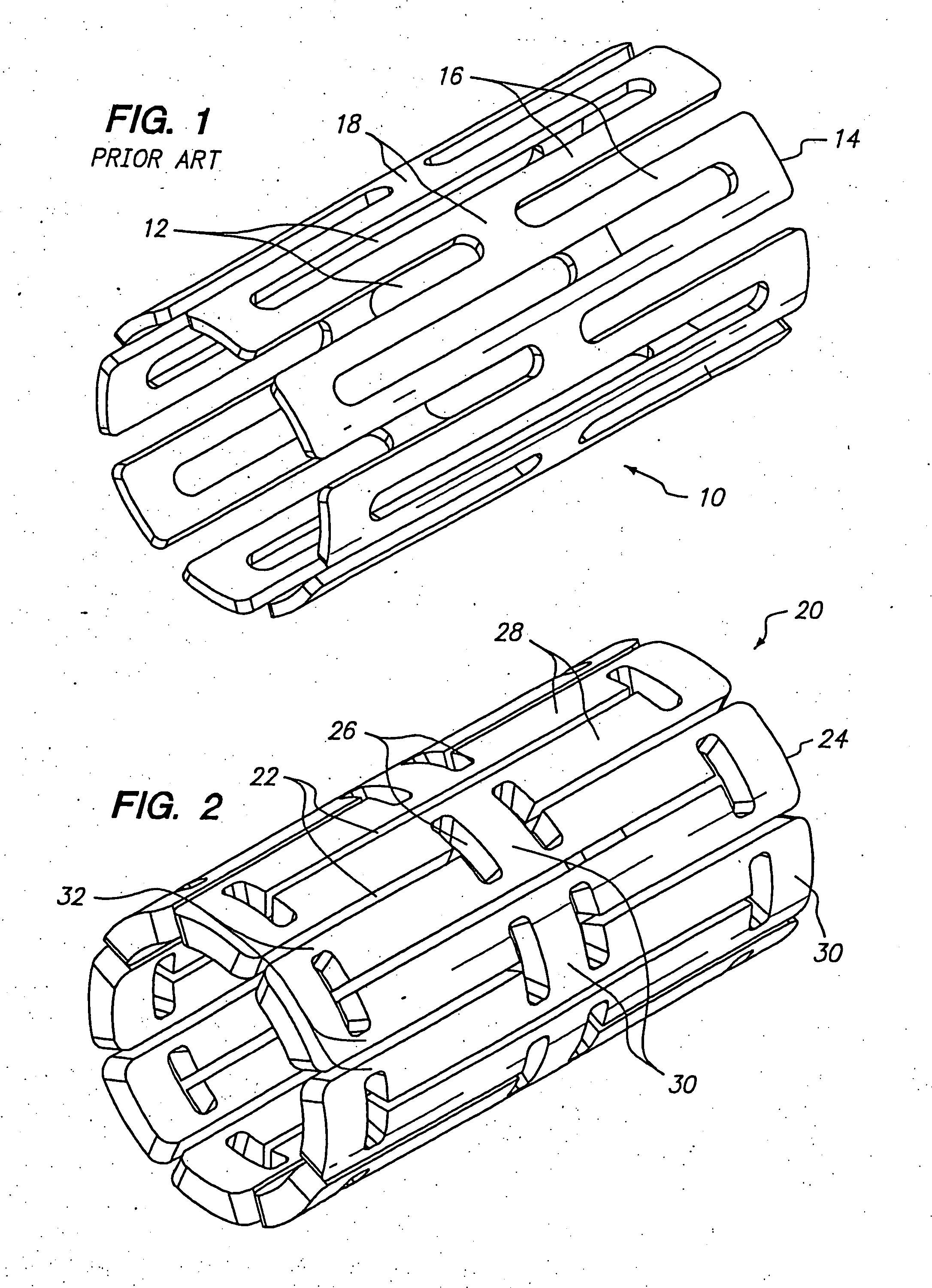
[0041]FIG. 2 shows one embodiment of an expandable tissue supporting device 20 in accordance with the present invention. The tissue supporting device 20 includes a series of axial slots 22 formed in a cylindrical tube 24. Each axial slot 22 is displaced axially from the slots in adjacent rows of slots by approximately half the slot length resulting in a staggered slot arrangement. The offset between adjacent rows of slots results in alternate rows of slots which extend to the ends of the cylindrical tube 24. At each interior end of each of the axial slots 22 a circumferential slot 26 is formed. The material between the slots 22 forms a network of axial struts 28 extending substantially parallel to an axis of the tube 24. The axial struts 28 are joined by short circumferential links 30. The circumferential links 30 are positioned at both the interior of the cylindrical tube and at the ends of the cylindrical tube. The cross section (and rectangular moment of inertia) of each of the s...


PUM


Abstract

An expandable tissue supporting device of the present invention employs ductile hinges at selected points in the expandable device. When expansion forces are applied to the device as a whole, the ductile hinges concentrate expansion stresses and strains in small well defined areas. The expandable medical device including ductile hinges provides the advantages of low expansion force requirements, relatively thick walls which are radio-opaque, improved crimping properties, high crush strength, reduced elastic recoil after implantation, and control of strain to a desired level. The expandable tissue supporting device includes a plurality of elongated beams arranged in a cylindrical device and connected together by a plurality of ductile hinges. Although many ductile hinge configurations are possible, the ductile hinges preferably have a substantially constant hinge cross sectional area which is smaller than a beam cross sectional area such that as the device is expanded from a first diameter to a second diameter, the ductile hinges experience plastic deformation while the beams are not plastically deformed.

Description

BACKGROUND OF THE INVENTION [0001] 1. Field of the Invention [0002] The present invention relates to tissue-supporting medical devices, and more particularly to expandable, non-removable devices that are implanted within a bodily lumen of a living animal or human to support the organ and maintain patency. [0003] 2. Summary of the Related Art [0004] In the past, permanent or biodegradable devices have been developed for implantation within a body passageway to maintain patency of the passageway. These devices are typically introduced percutaneously, and transported transluminally until positioned at a desired location. These devices are then expanded either mechanically, such as by the expansion of a mandrel or balloon positioned inside the device, or expand themselves by releasing stored energy upon actuation within the body. Once expanded within the lumen, these devices, called stents, become encapsulated within the body tissue and remain a permanent implant. [0005] Known stent des...

Claims


Application Information

Patent Timeline
Patent Type & Authority Applications(United States)
IPC IPC(8): A61F2/00A61F2/06A61F2/84
CPCA61F2/91A61F2/915A61F2002/91541A61F2250/0068A61F2250/0018A61F2250/0029A61F2250/0036A61F2002/91558A61M29/00
Inventor SHANLEY, JOHN F.
Owner INNOVATIONAL HLDG LLC
Why Eureka
Try Eureka