
Eureka
For R&D, Eureka makes reading and utilizing patents & technical documents easy.
Eureka AIR
Designed for self-driven R&D workflows. Generate viable solutions, solve complex R&D challenges, empower your innovation with AI.

Eureka Materials
Designed for material experts only. Revolutionize your material R&D, from search, analyze, to developing new materials.

TechResearch
Generate reliable direction feasibility study reports for your R&D in just a few steps.

TechSeek
Discover and master advanced knowledge NOW. Basics, ideas, possibilities, all at once.

TechMind
As an expert in R&D Theories, TechMind can generates customized viable solutions instantly.

TechRisk
Analyze your overall solution with one click, know your potential R&D risks in advance.

TechMonitor
Get weekly tech updates, stay abreast of the latest tech innovations and key insights.
Pedestal system
- Summary
- Abstract
- Description
- Claims
- Application Information
AI Technical Summary
Benefits of technology
Problems solved by technology
Method used
Image

Examples
first embodiment
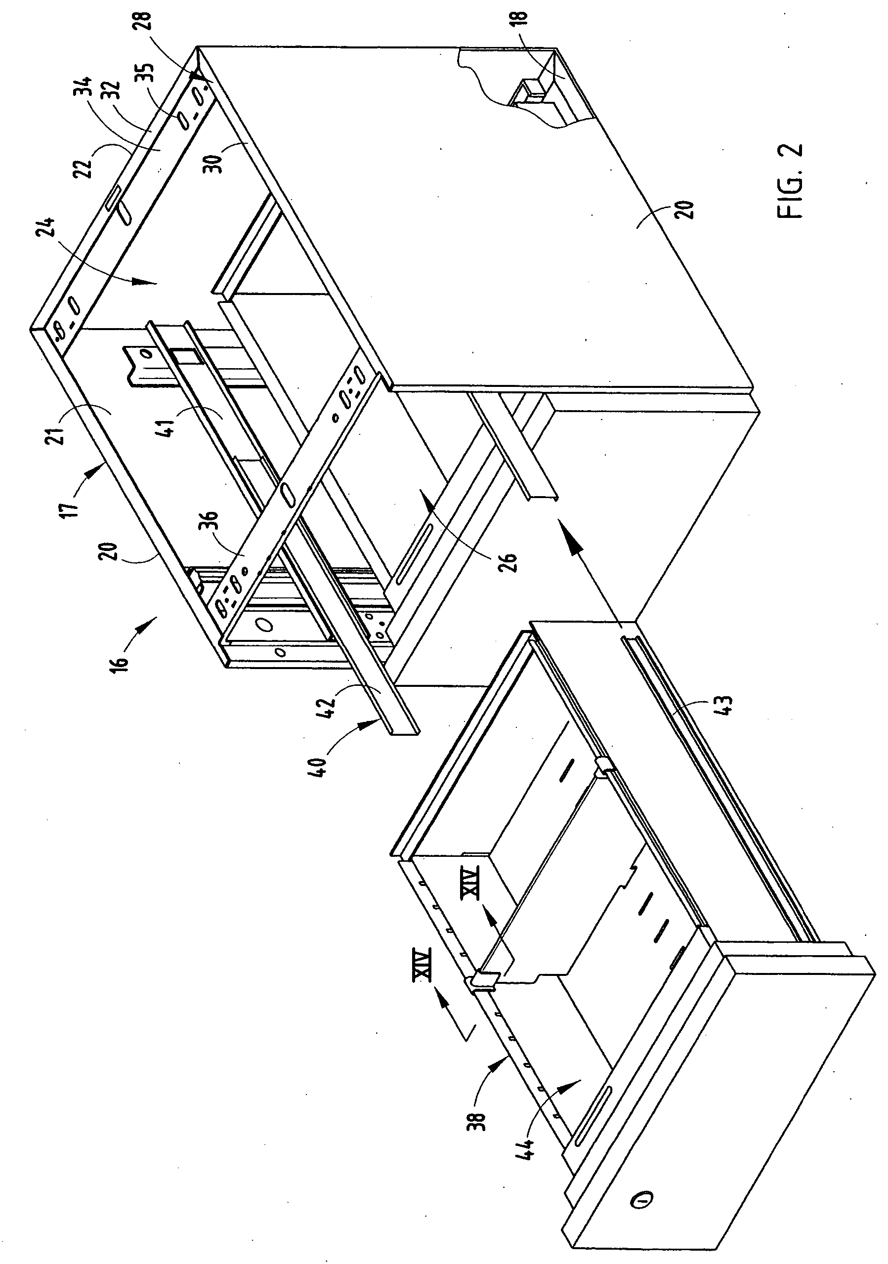
[0061] In a first embodiment, the housing 17 (FIGS. 3A and 3B) of each pedestal system 16 is coupled with a post member 52 of the partition assembly 12 by a coupling assembly 62. The coupling assembly 62 includes an L-shaped first mounting bracket 64 having an elongated, planar body portion 66 and a coupling flange 68 extending orthogonally and rearwardly from the body portion 66. The body portion 66 includes a plurality of apertures 67 extending therethrough. The coupling flange 68 includes a plurality of rearwardly-extending T-shaped tabs 70 extending along the length of the first mounting bracket 64. The coupling assembly 62 further includes a second mounting bracket 72 having a planar body portion 74, a coupling flange 76 extending rearwardly from and orthogonally to the body portion 74, a top flange 78 located near an end of the body portion 74 and extending laterally across and orthogonally thereto, and a bottom flange 79 located near an end of the body portion 74 opposite the...
second embodiment
[0063] In a second embodiment, a coupling assembly 90 is utilized to couple the housing 17 of the associated pedestal system 16 to the partition assembly 12. The coupling assembly 90 includes a first mounting bracket 92, a second mounting bracket 94, and a wedge 96. The first mounting bracket 92 is L-shaped and includes a planar body portion 98 and a coupling flange 100 extending rearwardly from and orthogonally to the body portion 98. The body portion 98 includes a plurality of apertures 99 extending therethrough. The first mounting bracket 92 further includes a plurality of T-shaped tabs 102 spaced along the length of and extending rearwardly from the coupling flange 100. The second mounting bracket 94 is L-shaped and includes a body portion 104 having a pair of laterally-extending slots 106, and a coupling flange 108 extending rearwardly from and orthogonally to the body portion 104. The coupling flange 108 includes a pair of rearwardly-facing, rectangularly-shaped, spaced-apart ...
third embodiment
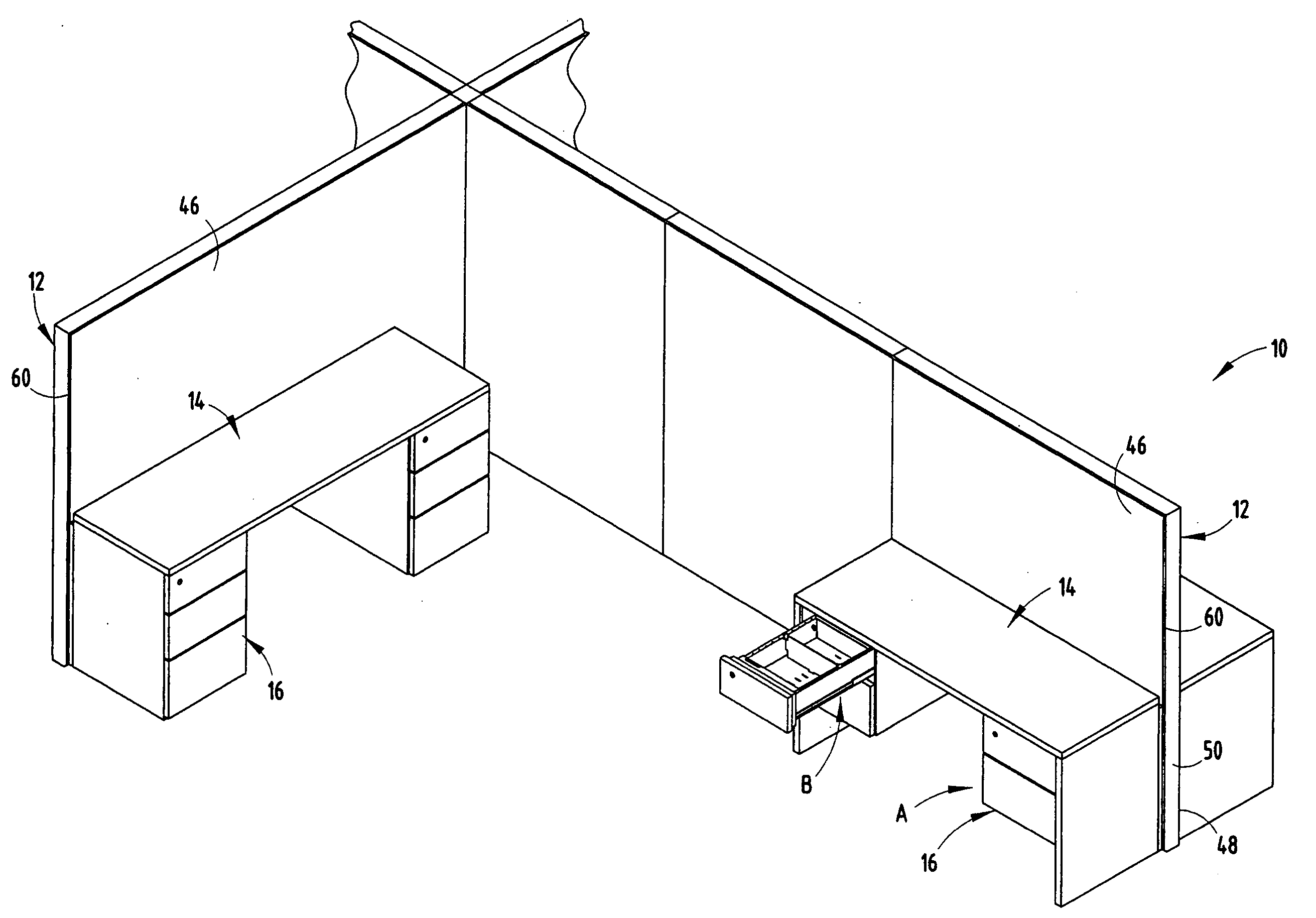
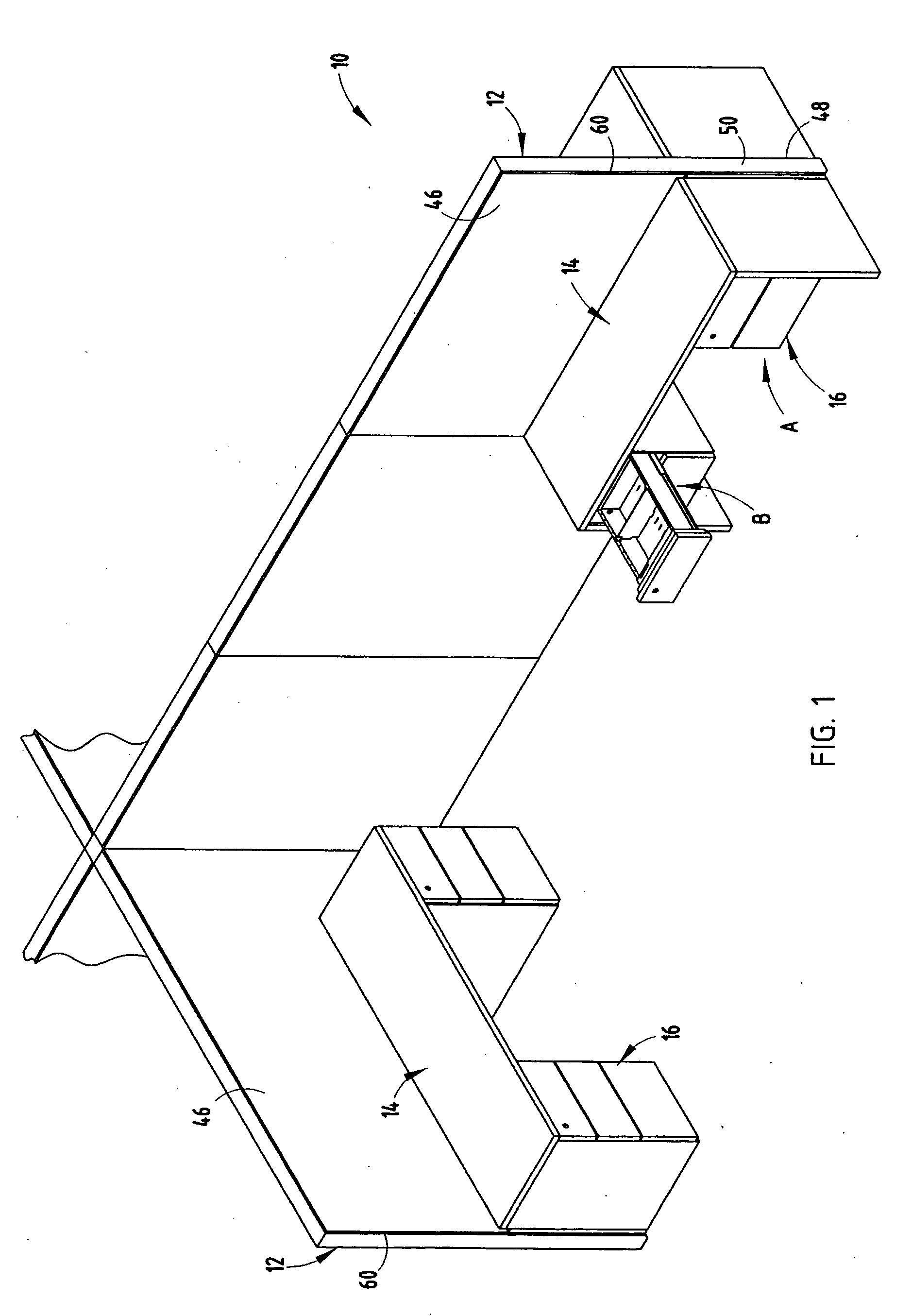
[0065] In a third embodiment, the pedestal system 16 (FIG. 8) may be hangingly supported from an associated worksurface 14. The worksurface 14 includes a top surface 120, a bottom surface 122, ends 124, a front edge 126, and a rear edge 128. The worksurface 14 (FIG. 1) may be supported at either end 124 by an end wall 130 extending between the floor and the associated end 124 to which the end wall 130 is secured, a pedestal system 16, or may be secured to the partition assembly 12 along the rear edge 128 of the worksurface 14 in a manner as is known in the art. In the illustrated example, a first support bracket 132 is affixed to the bottom surface 122 of the worksurface 14 and extends longitudinally therealong proximate the rear edge 128. The first support bracket 132 (FIG. 11D) includes a plurality of slots 134 extending along the length thereof. A second support bracket 140 extends longitudinally along and is affixed to the bottom surface 122 of the worksurface 14. The second sup...
PUM
 Abstract
Description
Claims
Application Information
 - R&D Engineer
- R&D Manager
- IP Professional
- Industry Leading Data Capabilities
- Powerful AI technology
- Patent DNA Extraction
Browse by: Latest US Patents, China's latest patents, Technical Efficacy Thesaurus, Application Domain, Technology Topic, Popular Technical Reports.
© 2024 PatSnap. All rights reserved.Legal|Privacy policy|Modern Slavery Act Transparency Statement|Sitemap|About US| Contact US: help@patsnap.com