Reduction gear and reduction gear frictional load application member

a technology of frictional load and reduction gear, which is applied in the direction of gearing, circuit electrostatic discharge protection, hoisting equipment, etc., can solve the problems of difficult to ensure a space, and likely cause of positional interference with another gear, etc., to reduce rattle noise, reduce cost, and simple structure

Inactive Publication Date: 2005-09-22
SUMITOMO HEAVY IND LTD
View PDF9 Cites 5 Cited by
  • Summary
  • Abstract
  • Description
  • Claims
  • Application Information

AI Technical Summary

Benefits of technology

[0020] A frictional load can be applied to a specific shaft of a reduction gear with a simple structure, thereby reducing rattle noises at low cost.

Problems solved by technology

However, there is a problem that the presence of a play induces so-called “rattle noises” in operation under a small load.
Therefore, there is a problem that positional interference with another gear is likely to be caused.
In particular, if a number of gears are present in the gear case 16 as in the case of a multistage reduction gear, it is often difficult to ensure a space where the oil seal 20 for generating a frictional load is to be provided.
The structure shown in FIG. 5(B) has also a problem that a space is difficult to be ensured if the size is small.
Therefore, it is sometimes difficult to house the O-ring 32 of desired size.
As a result, the structure is more complicated.

Method used


Image

  • Reduction gear and reduction gear frictional load application member
  • Reduction gear and reduction gear frictional load application member
  • Reduction gear and reduction gear frictional load application member

Examples


Embodiment Construction

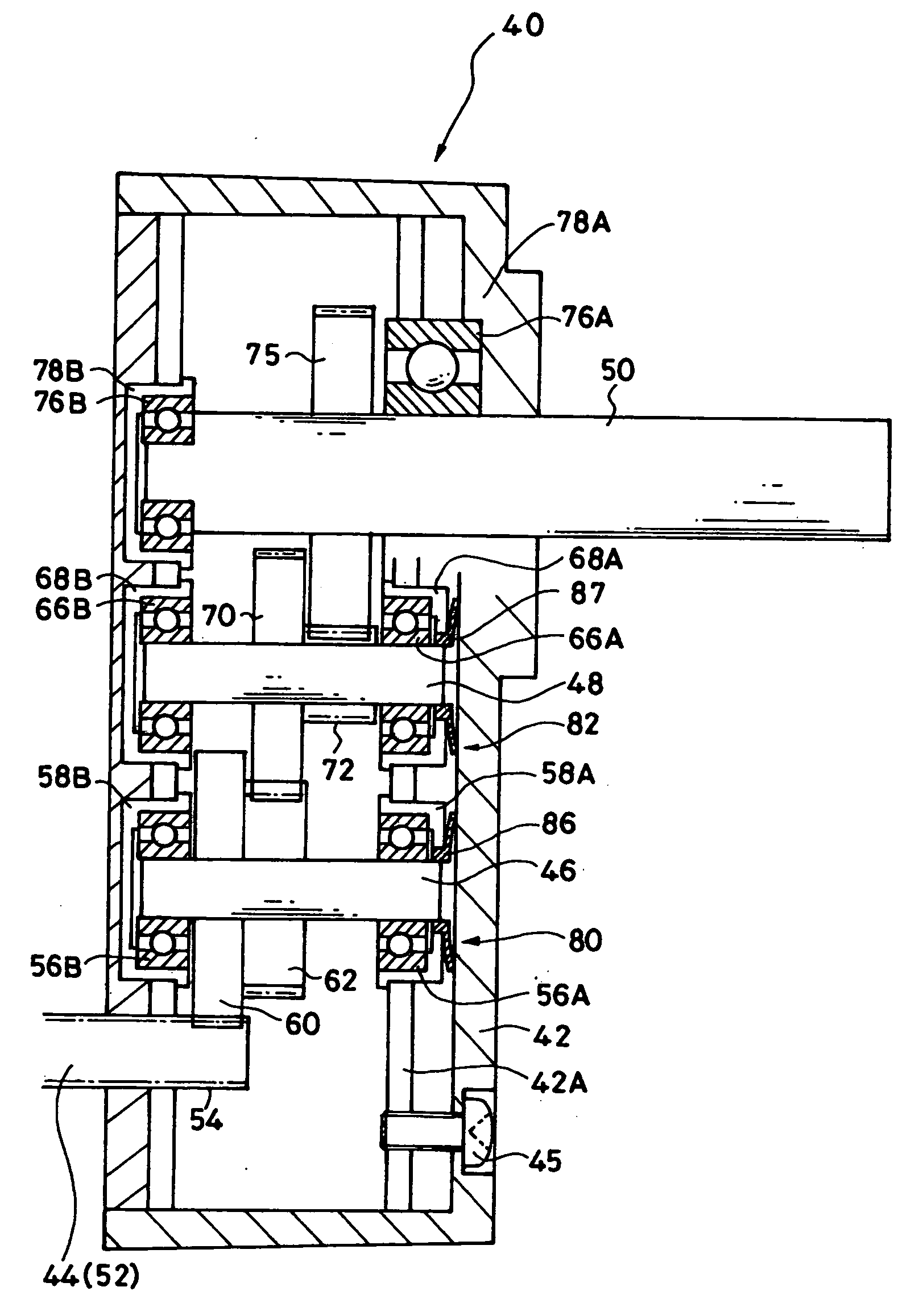
[0027] Hereinafter, examples of a multistage reduction gear with the application of various exemplary embodiments of this invention will be hereinafter described in detail with reference to the drawings.

[0028] A multistage reduction gear 40 includes an input shaft 44, a first intermediate shaft 46, a second intermediate shaft 48, and an output shaft 50.

[0029] In this exemplary embodiment, a motor shaft 52 of a motor (not shown) also serves as the input shaft 44. The input shaft 44 is exposed in a gear case 42 in a cantilever state. A first pinion 54 is formed at the tip of the input shaft 44 by direct gear cutting. The gear case 42 is connected with a side plate 42A forming a framework of the gear case 42 through a bolt 45.

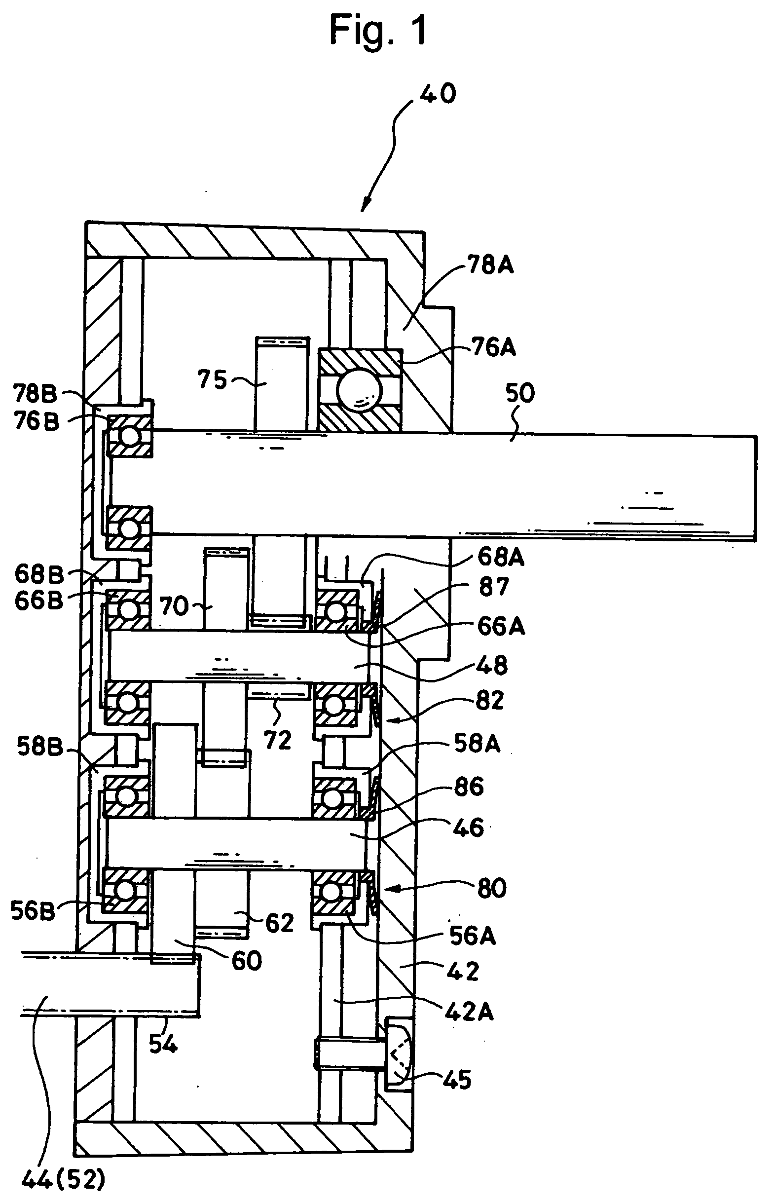
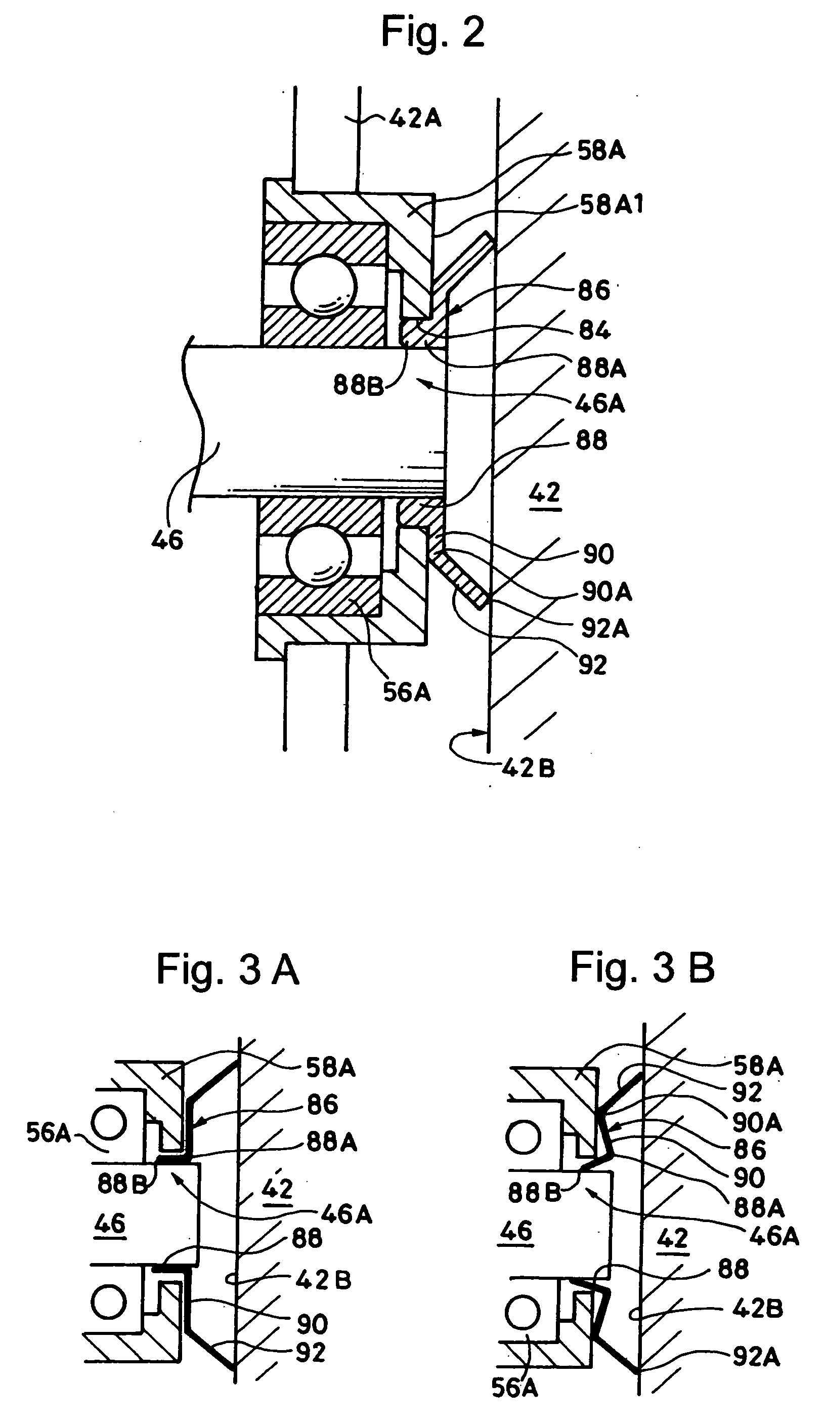
[0030] The first intermediate shaft 46 is supported by a pair of bearings 56A and 56B. The bearings 56A and 56B are housed in bearing housings 58A and 58B, respectively. The first intermediate shaft 46A has a first gear 60 meshing with the first pinion 54 and a...


PUM


Abstract

A reduction gear includes a gear case, a plurality of shafts in the gear case, a fixed member, an axially movable member, and a friction applying member. The friction applying member is interposed between the fixed member and the axially movable member, to apply a frictional force to at least one of the plurality of shafts in a radial direction of the shaft.

Description

BACKGROUND OF THE INVENTION [0001] 1. Field of the Invention [0002] The present invention relates to a reduction gear capable of reducing so-called rattle noises and a frictional load application (or generation) member for the reduction gear. [0003] 2. Description of the Related Art [0004] In a mechanical reduction gear, a “play” is provided between gears. The play is indispensable for smooth rotation of the gears. However, there is a problem that the presence of a play induces so-called “rattle noises” in operation under a small load. [0005] The rattle noise designates a noise generated by the repeated contact and separation between the tooth surface of a driving-side gear and the tooth surface of a driven-side gear due to the vibration or pulsation of a motor, a variation in load on the driven object side, or the like. [0006] In order to reduce such rattle noises, for example, Japanese Patent Laid-Open Publication No. 2002-115754 discloses a structure for applying a light friction...

Claims


Application Information

Patent Timeline
Patent Type & Authority Applications(United States)
IPC IPC(8): F16H48/06F16H55/14F16H55/18F16H57/02F16H57/028F16H57/029F16H57/03F16H57/12
CPCF16H57/0006Y10T74/19233F16H57/021A44C25/00H05K1/0259
Inventor HAGA, TAKASHITAMURA, MITSUHIRO
Owner SUMITOMO HEAVY IND LTD
Why Eureka
Try Eureka