Electrical conductor cable and method for forming the same

Inactive Publication Date: 2005-09-22
GIFT TECH LP
View PDF18 Cites 13 Cited by
  • Summary
  • Abstract
  • Description
  • Claims
  • Application Information

AI Technical Summary

Benefits of technology

[0021] Another significant advantage of the present invention is the fact that the conductor cable can be used in precisely those locations where conventional cables are presently used and they can be mounted in precisely the same manner. Thus, the substitution of the cable of the present invention can be accomplished easily, at low cost and, more importantly, with existing cable laying equipment.
[0022] Yet another significant advantage of the multiple component core is the damping effect of the components. The friction between surfaces of the individual core components has a damping force on the vibrations caused by the wind.
[0023] Yet another significant advantage of the present invention is that the materials used to comprise the core of the electrical conductor cable have a coefficient of thermal expansion that is about half that of steel. This lower coefficient of thermal expansion in the core combines with that of the conductive material, and by the law of mixtures provides a cable that expands less (and therefore, sags less) than conventional conductor cables employing steel or any other material having a greater coefficient of thermal expansion than the materials used in the present invention.
[0024] This present invention there

Problems solved by technology

Thermoplastics and fiberglass have both been used to support conductor cables, but both materials exhibit a tendency to sag over time.
However, core components exhibiting sufficient rigidity to bear the load of the

Method used


Image

  • Electrical conductor cable and method for forming the same
  • Electrical conductor cable and method for forming the same

Examples


Embodiment Construction

[0040] The current invention teaches a electrical conductor cable wherein a central support core comprises a plurality of individual cylindrically shaped core components which are non-conductive, and a conductive member is located on an outer surface of the core, and a method of forming the same.

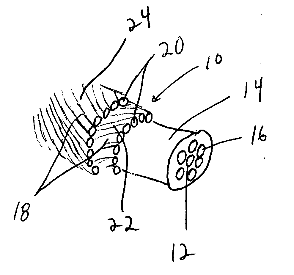
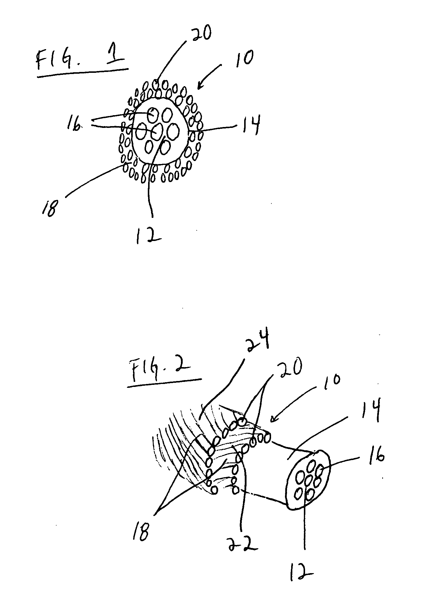
[0041]FIG. 1 shows an end view of an embodiment of the present invention. A electrical conductor cable 10 is shown. The electrical conductor cable 10 includes a core 12 having an outer sheath 14 and core components 16. The cable 10 further includes a conductive outer surface 18 which is placed on the outer sheath 14 of the core 12.

[0042] The core components 16 of the core 12 can be formed by reinforced plastic composites, carbon fiber composites, or glass composites, or any combination thereof. The materials used to form the core components 16 may be impregnated with resin and cured by any known method, including curing during a pultrusion process or by ultraviolet light. The core componen...


PUM


Abstract

An electrical conductor cable for long distance transmission of electrical current is provided. The conductor cable includes a plurality of individual cylindrically shaped non-conductive components. The conductor cable further includes an electrically conductive member located on an exterior of the core. A method for forming such a conductor cable is also provided.

Description

CROSS-REFERENCE TO RELATED APPLICATION(S) [0001] This is an ordinary application which is based upon and claims priority to U.S. Provisional Application No. 60 / 554,287, filed Mar. 17, 2004, the contents of which are fully incorporated herein by reference.BACKGROUND OF THE INVENTION [0002] The present invention is related to the field of electrical conductor cables designed to transmit electrical power between supporting poles or towers, and more specifically to electrical conductor cables and to methods of forming the same. [0003] The prior art teaches electrical transmission conductors formed of a steel component or supporting member designed to carry the entire cable which includes an electrical conductor such as aluminum or copper conductor. Usually, the conductor is enclosed within an outer sheath of the steel supporting member. [0004] In recent years, there has been an increased interest in electrical cables in which there is a reinforced plastic composite component capable of ...

Claims


Application Information

Patent Timeline
IPC IPC(8): H01B5/10H01B9/00H01B9/02
CPCH01B9/008H01B5/105
Inventor BROWNING, RAYMONDMCQUARRIE, TERRY S.
Owner GIFT TECH LP
Why Eureka
Try Eureka