Electric warmer with a current sensor

a current sensor and electric heater technology, applied in the field of electric warmers, can solve the problems of unnecessary supply of heating power, insufficient accuracy of filling, and significant safety drawbacks, and achieve the effect of low cos

Inactive Publication Date: 2005-09-22
DAVID & BAADER DBK
View PDF11 Cites 5 Cited by
  • Summary
  • Abstract
  • Description
  • Claims
  • Application Information

AI Technical Summary

Benefits of technology

[0006] An improved electric warmer of the above-mentioned type is provided wherein power can be supplied in a particularly efficient manner while the control device may be fabricated at particularly low costs at the same time.

Problems solved by technology

In this process, however, heating power may unnecessarily be supplied if heating is continued when the whole amount of water has already evaporated.
This solution, however, has significant drawbacks in terms of safety.
This is difficult in the case of comparatively small volumes because small amounts of water (e.g. 10 ml to 20 ml) can most of the time not be filled with adequate accuracy with the measuring methods that are standard in the household sector.
If, as an alternative, a thermostat is used for controlling the heating power supply in said warmers, this has the drawback that control and temperature measurement are very complicated.

Method used


Image

  • Electric warmer with a current sensor
  • Electric warmer with a current sensor
  • Electric warmer with a current sensor

Examples


Embodiment Construction

[0014] The illustrated embodiments of the present invention will be described with reference to the figure drawings wherein like elements and structures are indicated by like reference numbers.

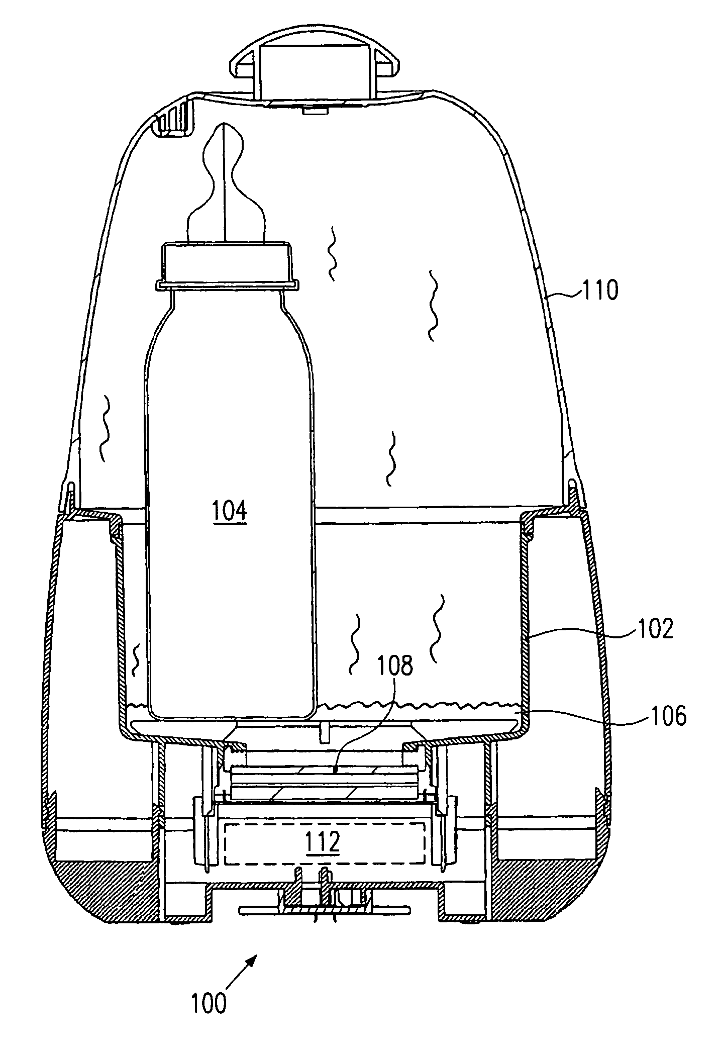
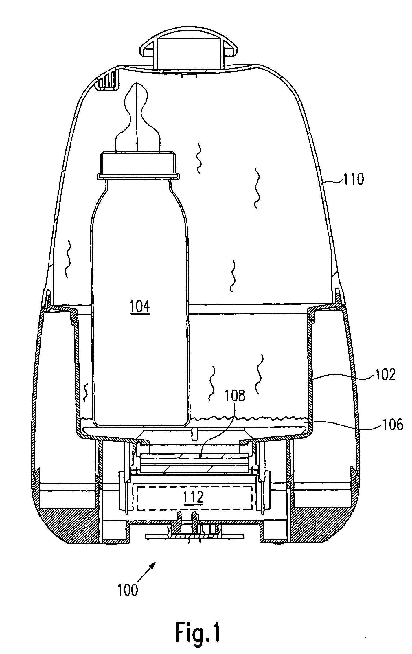
[0015] Referring now to the drawings and in particular to FIG. 1, a schematic illustration of an electric sterilizer 100 is shown in the operative state with an inserted baby bottle. The electric warmer comprises a jar 102 into which the container 104 to be heated, here e.g. a baby bottle, can be inserted. The jar 102 is filled with the heat transfer medium 106, here water, and a PTC resistor heating element 108 which is in thermal contact with water 106 can be fed with electrical energy for heating up the water. When the PTC resistor heating element 108 is heated, water 106 will heat up and start to evaporate.

[0016] To produce a closed vapor atmosphere for sterilizing the container 104, the jar is closed with a cover 110. Power supply is controlled with the help of the schematically outline...


PUM


Abstract

The present invention relates to an electric warmer for heating a container by means of a heat transfer medium. The warmer comprises a jar into which the container can be inserted for heating, and an electric heating device comprising at least one resistance heating element for heating the heat transfer medium. To indicate an improved electric warmer of the above-mentioned type in which power can be supplied in a particularly efficient manner while the control device can be configured at particularly low costs at the same time, the warmer comprises a sensor element for measuring the current flowing through the resistance heating element during operation of the heating device, and a control unit configured in such a manner that it detects a typical change in the current flowing through the resistance heating element due to a change in the state of aggregation of the medium to be heated, and controls power supply to the resistance heating element in dependence upon the state of aggregation of the medium to be heated.

Description

FIELD OF THE INVENTION [0001] The present invention relates to an electric warmer for heating a container by means of a heat transfer medium, and in particular, to a warmer that comprises a jar into which the container can be inserted for heating, and an electric heating device comprising at least one resistance heating element for heating the heat transfer medium. BACKGROUND OF THE INVENTION [0002] Presently, vaporization of water in an electric warmer is needed in so-called vaporizers, i.e. in sterilizers, for instance for baby bottles. The power supply in such devices is most of the time monitored and controlled via temperature monitoring, as is e.g. shown in U.S. Pat. No. 4,716,278. In this process, however, heating power may unnecessarily be supplied if heating is continued when the whole amount of water has already evaporated. [0003] A further known arrangement of a sterilizer is shown in U.S. Pat. No. 3,347,618. In this sterilizer, the heating power is switched off directly a...

Claims


Application Information

Patent Timeline
Patent Type & Authority Applications(United States)
IPC IPC(8): A47J36/24F24C7/10
CPCA47J36/2438
Inventor BAUER, HANS-PETER
Owner DAVID & BAADER DBK
Why Eureka
Try Eureka