Container sealing structure, container with the sealing structure, and method of manufacturing the sealing structure

a technology of sealing structure and container, applied in the field of sealing structure, can solve the problems of cap removal from the container, unsanitary situation, worsening productivity, etc., and achieve the effect of easy breakage of the portion

Inactive Publication Date: 2005-09-22
TOYO SEIKAN KAISHA LTD
View PDF9 Cites 46 Cited by
  • Summary
  • Abstract
  • Description
  • Claims
  • Application Information

AI Technical Summary

Benefits of technology

[0011] A container sealing structure described in claim 1 is configured such that a pouring portion

Problems solved by technology

With respect to such a conventional hermetically sealed container, when some beverage remains in the container after drinking, it is unable to reseal the opening portion and hence, there have been drawbacks that it requires time and efforts to throw away the remaining beverage or to move the beverage in the container to a cup or the like and to preserve the beverage in a refrigerator and, at the same time, a foreign substance adheres to the lid thus easily giving rise to an unhygienic situation.
(1) There exists a drawback that since the resin made cap is constituted separately from the container body, steps for manufacturing the container become cumbersome thus worsening the productivity.
(2) There exist drawbacks that due to vibrations and impacts the container receives during the transportation before use or the like, there is a possibility that the cap is removed from the container body and, at the same time, the cap exhibits poor durability dur

Method used


Image

  • Container sealing structure, container with the sealing structure, and method of manufacturing the sealing structure
  • Container sealing structure, container with the sealing structure, and method of manufacturing the sealing structure
  • Container sealing structure, container with the sealing structure, and method of manufacturing the sealing structure

Examples


embodiment 1

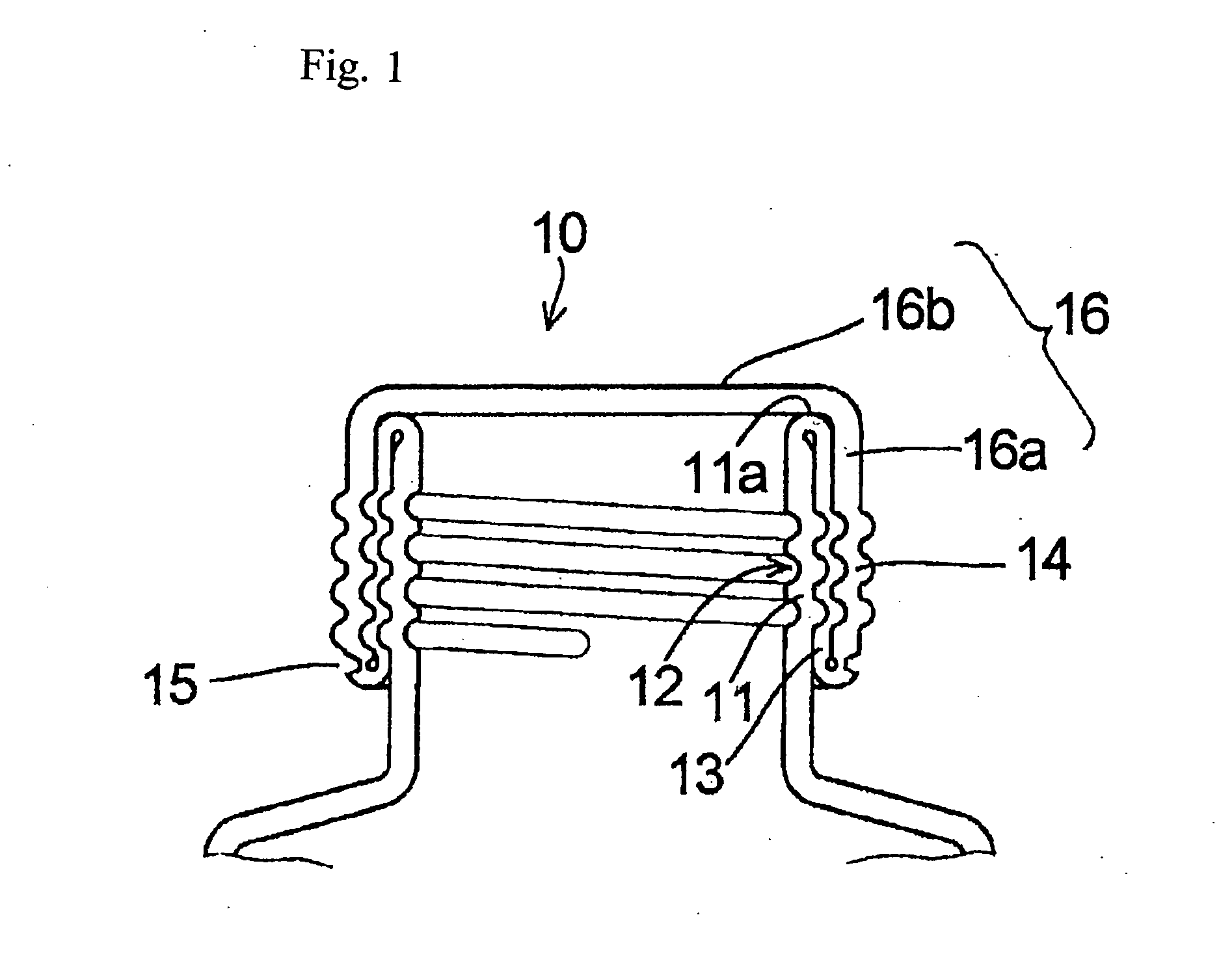
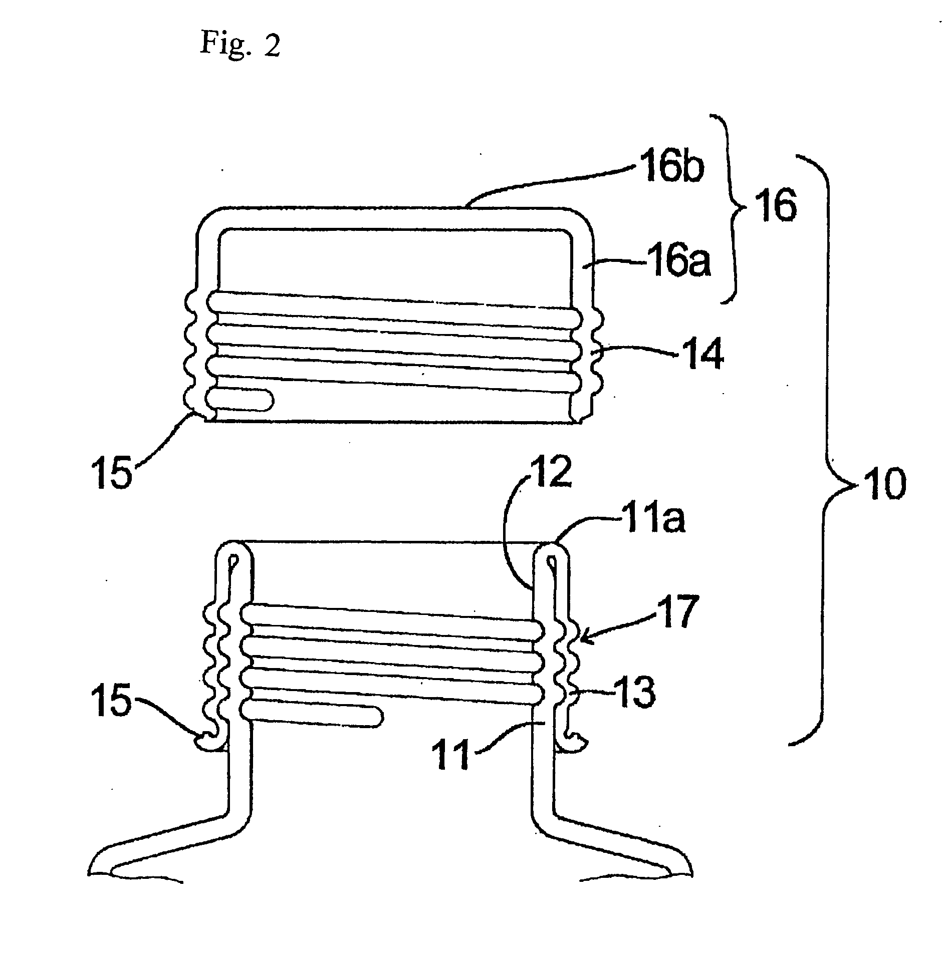
[0062]FIG. 1 is a cross-sectional view of an essential part of a container provided with a container sealing structure of an embodiment 1 of the present invention and FIG. 2 is a cross-sectional view of an essential part of the container in a state that a cap portion is separated.

[0063] In this embodiment 1, an example in which threads are formed in an inner wall, an intermediate wall and an outer wall is illustrated.

[0064] In FIG. 1 and FIG. 2, numeral 10 indicates the container sealing structure of the embodiment 1, numeral 11 indicates an inner wall, numeral 12 indicates a pouring portion, numeral 13 indicates an intermediate wall which is formed by folding back at an end portion 14a of the inner wall 11, numeral 14 indicates an outer wall which is formed by folding back upwardly from a lower end of the intermediate wall 13, numeral 15 indicates an easily breakable portion which is formed by providing scores in a thin-wall-thickness groove shape at a lower end side of the inter...

embodiment 2

[0084] The sealing structure 10(2) shown in FIG. 9 is, in the sealing structure of the above-mentioned embodiment 1, characterized in that the thread engaging portion 17 is formed on the inner wall 11 and the intermediate wall 13, while the outer wall 14 is formed into a flat cover portion 16a. A manufacturing method of the sealing structure 10(2) of the embodiment 2 is as follows.

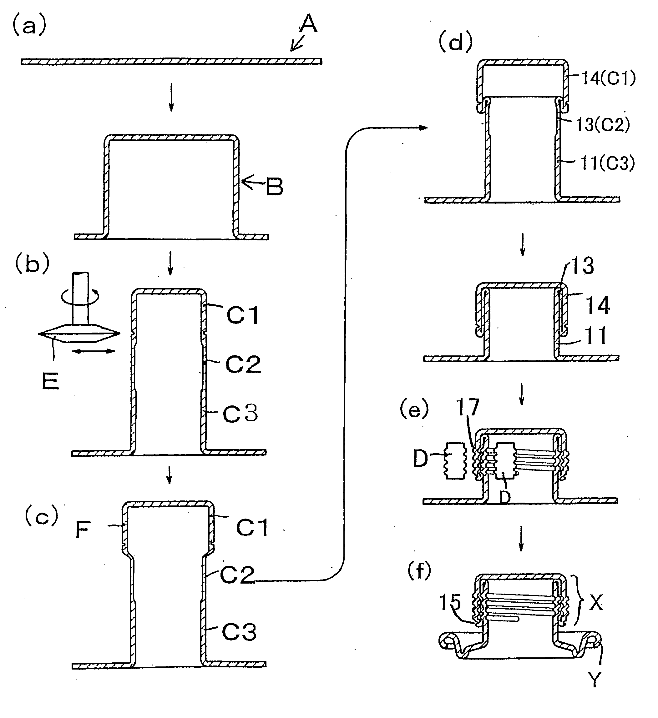
[0085] The cylindrical portion B shown in FIG. 10 is formed by an injection molding method or the like using a plastic material or the like as a material.

[0086] The cylindrical portion 10 (2a) is constituted of the upper portion C1 having a large diameter and the center portion C2 and the lower portion C3 having diameters smaller than the diameter of the upper-portion C1, wherein these portions are substantially coaxially and integrally formed.

[0087] Threads 17b are formed on the lower portion C3. Threads 17a having a threading direction opposite to the threading direction of the threads 17b and having ...

embodiment 3

[0091] The sealing structure 10(3) shown in FIG. 11 is, in the sealing structure of the above-mentioned embodiment 1, characterized in that thread engaging portions 17 are formed on an outer wall 14 and an intermediate wall 13 and an inner wall 11 is formed into a flat pouring portion 12. A manufacturing method of such a sealing structure 10(3) of the embodiment 3 is as follows.

[0092] A cylindrical portion 10(3a) shown in FIG. 12 is formed by an injection molding method using a plastic material or the like as a material.

[0093] The cylindrical portion 10 (3a) is constituted of an upper portion C1 having a large diameter and a center portion C2 and a lower portion C3 having a diameter smaller than the diameter of the upper portion C1, wherein these portions are formed substantially coaxially and integrally.

[0094] Threads 17d and an easily breakable portion 17 are formed in the upper portion C1. Threads 17c having a threading direction opposite to a threading direction of the thread...


PUM


Abstract

A task of the present invention is to provide a container sealing structure capable of easily and surely unsealing a container and hygienically maintaining an opening portion at the time of resealing, and a method of manufacturing the sealing structure. The container sealing structure of the present invention is configured by integrally forming a pouring portion (12) and a cap portion (16). An easily breakable portion (15) is formed in the container sealing structure. The pouring portion (12) and the cap portion (16) includes an intermediate wall (13) which is formed by bending downwardly from an upper end portion of an inner wall (11) and an outer wall (14) which is formed by bending upwardly from a lower end portion of the intermediate wall (13).

Description

TECHNICAL FIELD [0001] The present invention relates to a sealing structure of a beverage container such a beverage can, a plastic bottle or the like, a petroleum can or the like, and more particularly a container sealing structure which enables easy unsealing and resealing after unsealing, a container provided with the sealing structure and a method of manufacturing the sealing structure. BACKGROUND ART [0002] As a hermetically sealed container such as a juice can, a beer can, a carbonate beverage can, a coffee beverage can, a black tea beverage can or the like, a container which seams an easily openable lid to an opening end portion of a container body has been popularly used. An easily breakable portion (scores) which defines an opening portion (pouring portion) is formed in the easily openable lid, wherein by breaking and pushing the easily breakable portion downward using a pinching tab which is fixedly mounted on a lid body by riveting, an opening portion which constitutes an ...

Claims


Application Information

Patent Timeline
IPC IPC(8): B21D51/46B21D51/50B65D1/02B65D41/34
CPCB21D51/46B65D41/34B65D1/0238B21D51/50B21D51/38B65D47/36
Inventor KOBAYASHI, TOMOMITAKAO, KENICHINAGATA, KOUJIKUROKAWA, WATARUTSUKADA, KAZUHIKO
Owner TOYO SEIKAN KAISHA LTD
Why Eureka
Try Eureka