Tuyere cooling system

Inactive Publication Date: 2005-09-22
ARCELORMITTAL DOFASCO
View PDF1 Cites 10 Cited by
  • Summary
  • Abstract
  • Description
  • Claims
  • Application Information

AI Technical Summary

Benefits of technology

[0007] A tuyere comprises a body section, a nose section and a cooling system. The cooling system includes a first coolant passageway extending through said body section and having an inlet and an outlet A second coolant passageway extending through the nose section and has an inlet

Problems solved by technology

This causes a delay in the manufacturing process while the tuyere is replaced.
However, by requiring two separate water circuits, the cost fo

Method used


Image

  • Tuyere cooling system
  • Tuyere cooling system
  • Tuyere cooling system

Examples


Embodiment Construction

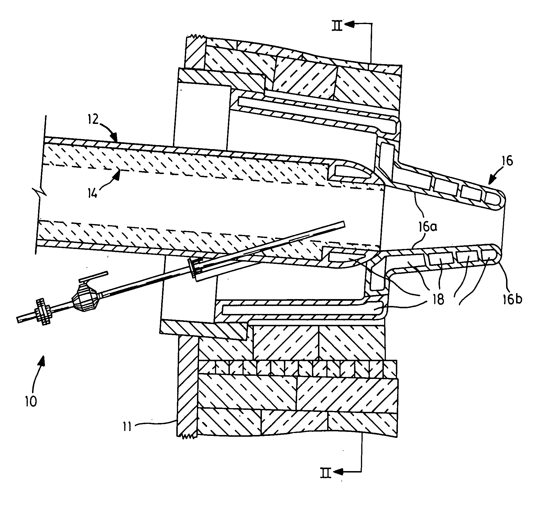
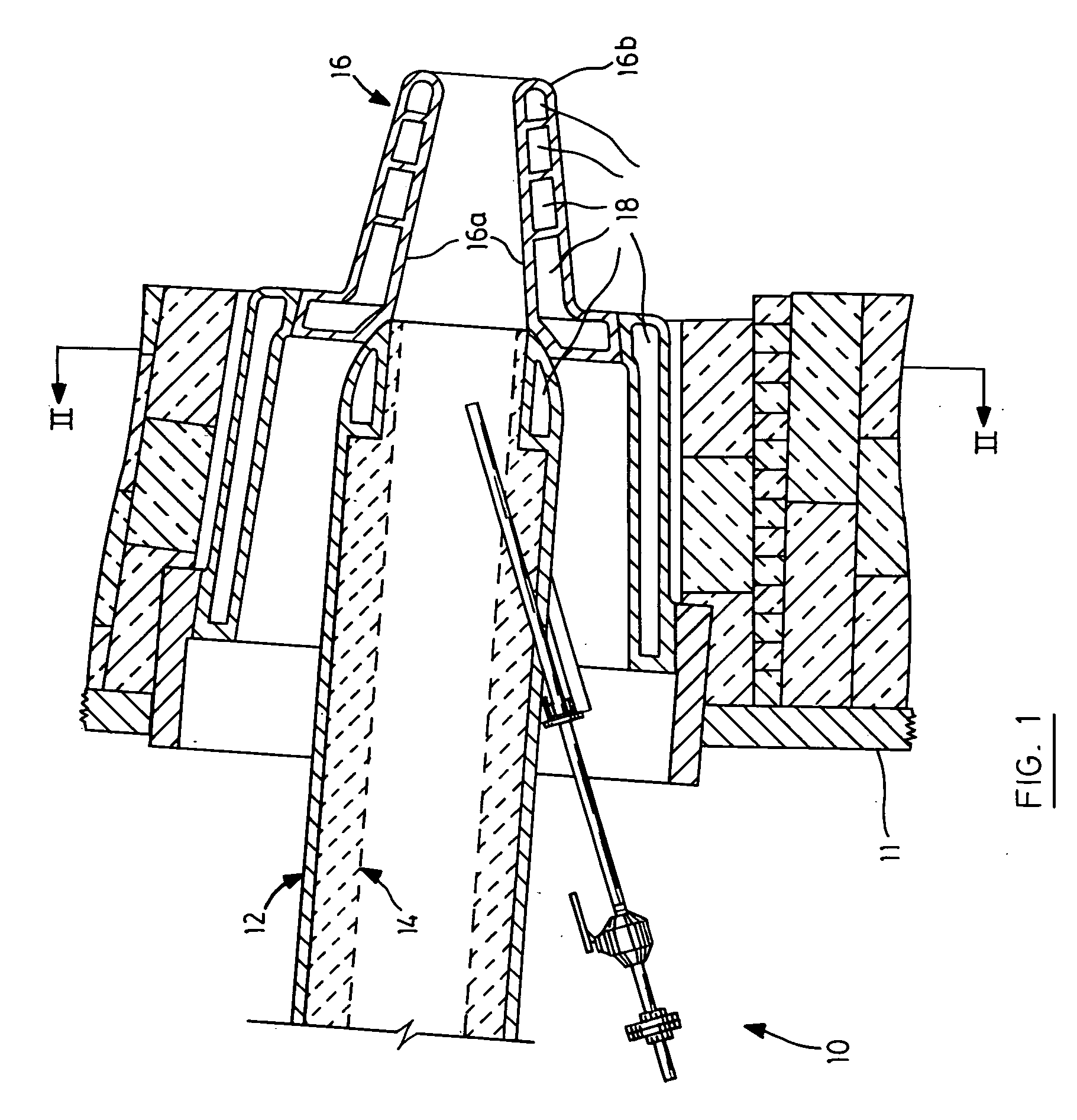
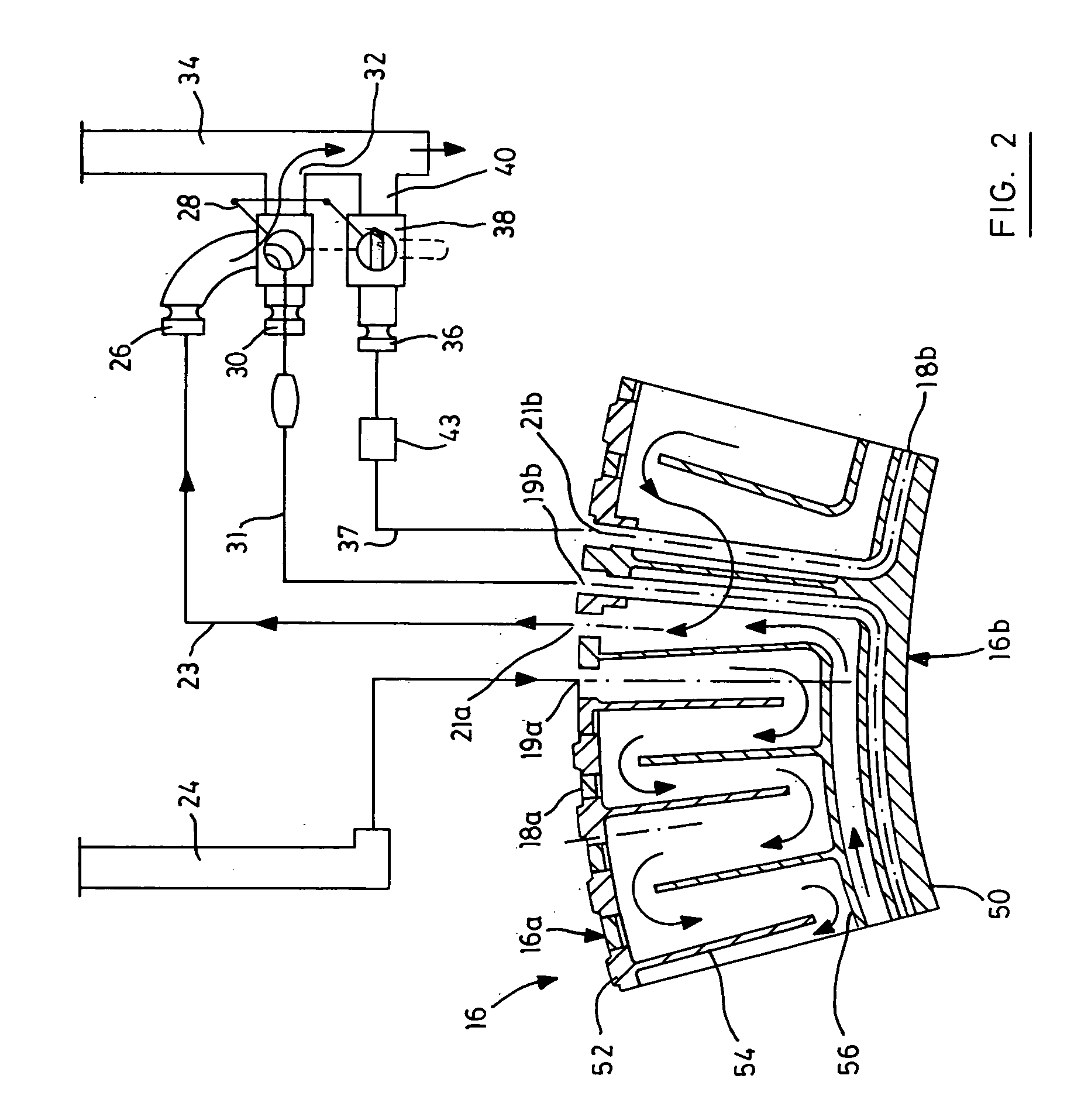
[0014] Turning to FIG. 1, a tuyere and blowpipe assembly 10, located within a wall 11 of a blast furnace, includes a blowpipe 12 with a ceramic lining 14 to introduce air into the furnace. The blowpipe 12 is connected to a tuyere 16 which is mounted in the wall 11. The tuyere 16 generally comprises a body section 16a and a nose section 16b. Passageway 18 within the tuyere 16 allows a fluid coolant, such as water, to pass through and cool the tuyere 16 during operation of the blast furnace. As shown in FIGS. 2 and 3, the passageway 18 is subdivided into two sets, a body passageway 18a for cooling the body section 16a and a nose passageway 18b for cooling the nose section 16b.

[0015] As may be more clearly seen in FIG. 3, body passageway 18a has an inlet 19a and an outlet 21a and forms a separate path through the body 16a of the tuyere while nose passageway 18b suitably has an inlet 19b and an outlet 21b and is located as an annular passage at the nose 16b of the tuyere 16. The passag...


PUM

PropertyMeasurementUnit
Flow rateaaaaaaaaaa

Abstract

A tuyere cooling system which includes a coolant circuit for a body section and nose section. A valve is operable to connect the coolant circuits in series or to disconnect flows to the nose section of the tuyere so that if the nose of the tuyere tears during operation, the flow of coolant to the nose section of the tuyere may be cut off without affecting the overall operation of the blast furnace.

Description

[0001] This application is a continuation of PCT application No. PCT / CA03 / 00766 filed on May 29, 2003, which claims priority from U.S. provisional application No. 60 / 383,777 filed on May 30, 2002 the contents of which are incorporated herein by reference.FIELD OF THE INVENTION [0002] The present invention relates in general to tuyeres, and, more specifically, to a tuyere cooling system. DESCRIPTION OF THE PRIOR ART [0003] The use of blast furnaces in the manufacture of metals has been well known for many years. Blast furnaces generally include a blowpipe which connects a hot-blast system with a tuyere which blows hot air into the hearth of the blast furnace. However, due to the high temperature (around 1100° C.) of the hot-blast system, the tuyere is required to be cooled during use in order to protect it from being overheated. [0004] In prior art tuyere cooling systems which only require one water circuit, if the nose section tears or breaks, the entire water circuit must be shut d...

Claims


Application Information

Patent Timeline
IPC IPC(8): C21B7/16F27B1/16F27B1/24F27D3/16F27D9/00F27D19/00F27D25/00F27D99/00
CPCC21B7/16C21B7/163F27B1/16F27B1/24F27D2099/0053F27D9/00F27D19/00F27D25/001F27D3/16
Inventor OHRT, HERMANGECAN, LOUGECAN, JENNIFER
Owner ARCELORMITTAL DOFASCO
Why Eureka
Try Eureka