
Clamping cylinder having a closure cap

a technology of closure cap and cylinder, which is applied in the direction of metal-working holders, large fixed members, supporters, etc., can solve the problems of difficult to accurately fit the draw-in bolt into the receptacle, difficult to achieve the effect of reducing the number of holes

Inactive Publication Date: 2005-09-22
VISCHER & BOLLI
View PDF3 Cites 5 Cited by
  • Summary
  • Abstract
  • Description
  • Claims
  • Application Information

AI Technical Summary

Benefits of technology

[0008] It is therefore the object of the present invention to configure a clamping device of the kind cited initially in such a way that the draw-in bolt can be easily inserted into the opening and is at the same time centered.
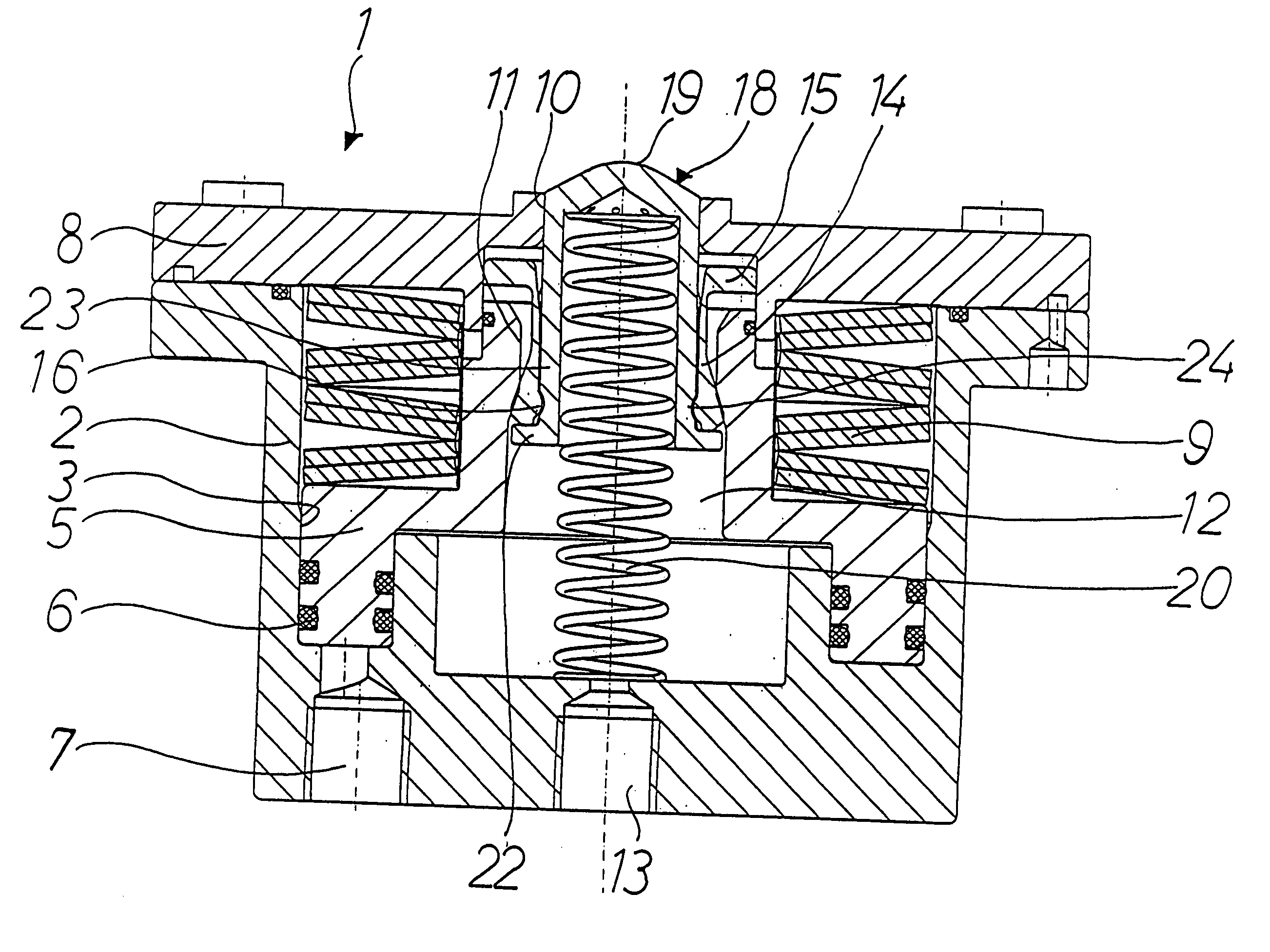
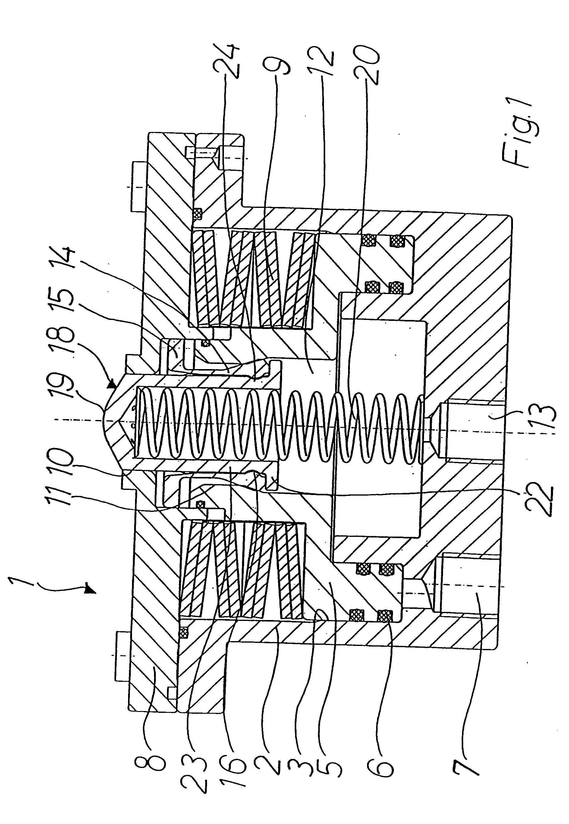
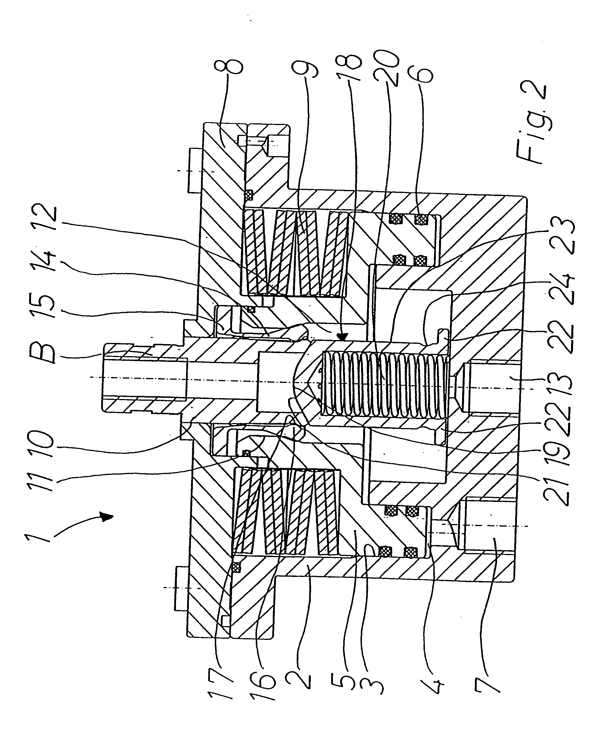
[0010] The invention is therefore based on the concept of automatically pre-centering the draw-in bolt, upon introduction into the receptacle, by way of the end surfaces of the draw-in bolt and closure cap that come into contact, so that minor offsets between the draw-in bolt and the receptacle are corrected. Even heavy workpieces can thus be easily and quickly clamped in place on the machine tool.
[0011] Advantageously, provision can be made for the end surfaces of the draw-in bolt and closure cap that come into contact with one another to be embodied as two corresponding centering surfaces. It is particularly favorable in this context to configure the end surface of the closure cap in dome-like fashion, and to configure the end surface of the draw-in bolt in a manner complementary to that dome-like end surface. End surfaces thus constituted achieve a good centering effect and are easy to manufacture.
[0012] In an embodiment of the invention, provision is further made for the closure cap to be pushed into the closed position by a spring or a hydraulic piston. Both embodiments ensure simple actuation and are robust.
[0015] With this embodiment of the invention, the closure cap can comprise in a side wall at least one recess or depression, for example in the form of an annular groove, into which at least one clamping tongue engages when the closure cap is in the closed position, in order to retain the closure cap. When the immobilization piston is in the immobilized position, the clamping tongues are immobilized in the clamping position and therefore the closure cap is also immobilized in the closed position, so that it can protect the receptacle from contamination.

Problems solved by technology

The machining of workpieces is often complex, and can encompass a plurality of chip-generating and non-chip-generating working steps on various processing machines in order to produce the finished component from a blank.
With the known clamping devices, it is regarded as disadvantageous to some extent that the draw-in bolt must be inserted in accurately fitted fashion into the receptacle.

Method used


Image

  • Clamping cylinder having a closure cap
  • Clamping cylinder having a closure cap
  • Clamping cylinder having a closure cap

Examples


Embodiment Construction

)

[0019]FIGS. 1 and 2 depict an embodiment of a clamping device 1 according to the present invention that serves to retain a draw-in bolt B on a machine table or the like. Clamping device 1 comprises a housing 2, embodied as a cylinder, that can be attached to the machine table or the like. An immobilization piston 5 is inserted, axially movably between an immobilized position and a release position, into cylinder bore 3 of housing 2 that opens toward the upper side of the housing, forming a pressure space 4; an annular gap between cylinder bore 3 and immobilization piston 5 is sealed with O-rings 6. A conduit 7, configured in housing 2, through which a hydraulic medium such as, for example, oil can be delivered to pressure space 4, opens into the bottom of cylinder bore 3.

[0020] The open upper side of housing 2 is closed off by a cover 8 that is attached to housing 2. Arranged between cover 8 and immobilization piston 5 are compression springs 9 that are braced between cover 8 and ...


PUM


Abstract

A clamping device for a machine table comprises a clamping plate having a receptacle into which a draw-in bolt is insertable through an opening. A clamping mechanism immobilizes the draw-in bolt in the receptacle. A closure cap is movable inside the receptacle between a closed position and an operating position in which the closure cap is pushed into the receptacle by the draw-in bolt. The draw-in bolt is inserted into the receptacle and immobilized with the clamping mechanism. A centering surface is implemented on the end surface of the closure cap facing toward the outer side of the clamping device and / or on the end surface of the draw-in bolt facing toward the inner side of the clamping device. The centering surface pre-centers the draw-in bolt when it is inserted into the receptacle and its end surface thereby comes into contact with the end surface of the closure cap.

Description

CROSS-REFERENCE TO RELATED APPLICATIONS AND CLAIM TO PRIORITY [0001] This application claims priority under 35 U.S.C. § 119 to Application Number 20 2004 004 181.2, filed Mar. 16, 2004 in the Federal Republic of Germany, the disclosure of which is incorporated herein by reference. FIELD OF THE INVENTION [0002] The present invention concerns a clamping device for retaining a draw-in bolt on a machine table, a clamping plate, or the like, having a receptacle into which a draw-in bolt is insertable from outside through an insertion opening; a clamping mechanism in order to immobilize the draw-in bolt in the receptacle; and a closure cap that is movable inside the receptacle between a closed position in which the insertion opening of the receptacle is closed off by the closure cap, and an operating position in which the closure cap is pushed into the receptacle by the draw-in bolt, which is inserted into the receptacle and immobilized with the clamping mechanism. BACKGROUND OF THE INVEN...

Claims


Application Information

Patent Timeline
Patent Type & Authority Applications(United States)
IPC IPC(8): B23B31/107B23Q1/00B23Q3/02B23Q3/18B23Q16/02
CPCB23Q1/0072B23Q16/021B23Q3/183
Inventor ETTER, ERNST
Owner VISCHER & BOLLI
Learn More