Sheet feeding apparatus, sheet feeding method and control program

a feeding apparatus and control program technology, applied in the direction of thin material processing, article separation, article delivery, etc., can solve the problems of frequent wrong feeding, double feeding, and limited types of actually applicable sheets, and achieve stable sheet feeding, low cost, and high performance.

Active Publication Date: 2005-09-22
CANON KK
View PDF26 Cites 41 Cited by
  • Summary
  • Abstract
  • Description
  • Claims
  • Application Information

AI Technical Summary

Benefits of technology

[0014] In view of the above-noted problems peculiar to the conventional art, the present invention has as its object to provide a sheet feeding apparatus and a sheet feeding method of high performance and low cost which can realize stable sheet feeding without being affected by the materials of sheets, a control program and an image forming apparatus for executing a controlling method for the sheet feeding apparatus.
[0026] Also, the computer-readable control program of the present invention for executing a controlling method for a sheet feeding apparatus for feeding sheets, the sheet feeding apparatus having a sheet tray on which sheets are stacked, a fan which blows air against the sheets so as to float up the sheets stacked on the sheet tray, a tray lifting and lowering mechanism which lifts and lowers the sheet tray, and a position detecting sensor which detects the position of the sheets floated up by the fan, and provided with an adjusting step of controlling the lifting and lowering operation of the tray lifting mechanism on the basis of the result of detection by the position detecting sensor to thereby adjust the position of the sheet tray.

Problems solved by technology

As this close contacting force between the sheets becomes greater, there occurs a case where it becomes impossible to effect sheet separation by the blowing of the air, and this has led to the problem that the types of actually applicable sheets are restricted to a certain extent.
Particularly under a high-temperature and high-humidity environment, such sheets of high smoothness as mentioned above, because of being very high in the close contacting force between sheets as compared with plain paper, have the possibility that double feed may occur frequently or feeding is not smoothly effected but wrong feeding may occur frequently.
In a case where any of these techniques is used, it is impossible to avoid an increase in the cost of the apparatus itself, and this has led to the problem that a sheet feeding apparatus of high performance cannot be realized at a low cost.

Method used


Image

  • Sheet feeding apparatus, sheet feeding method and control program
  • Sheet feeding apparatus, sheet feeding method and control program
  • Sheet feeding apparatus, sheet feeding method and control program

Examples


Embodiment Construction

[0044] Embodiments of the sheet feeding apparatus, the sheet feeding method and the control program of the present invention will hereinafter be described with reference to the drawings. The sheet feeding apparatus according to the present embodiment will be described as being applied to an air feeding unit carried on an image forming apparatus such as, for example, a color copying machine or a color printer, but is not restricted to such an apparatus. That is, it can be applied to all of apparatuses for feeding a cut sheet to a predetermined position.

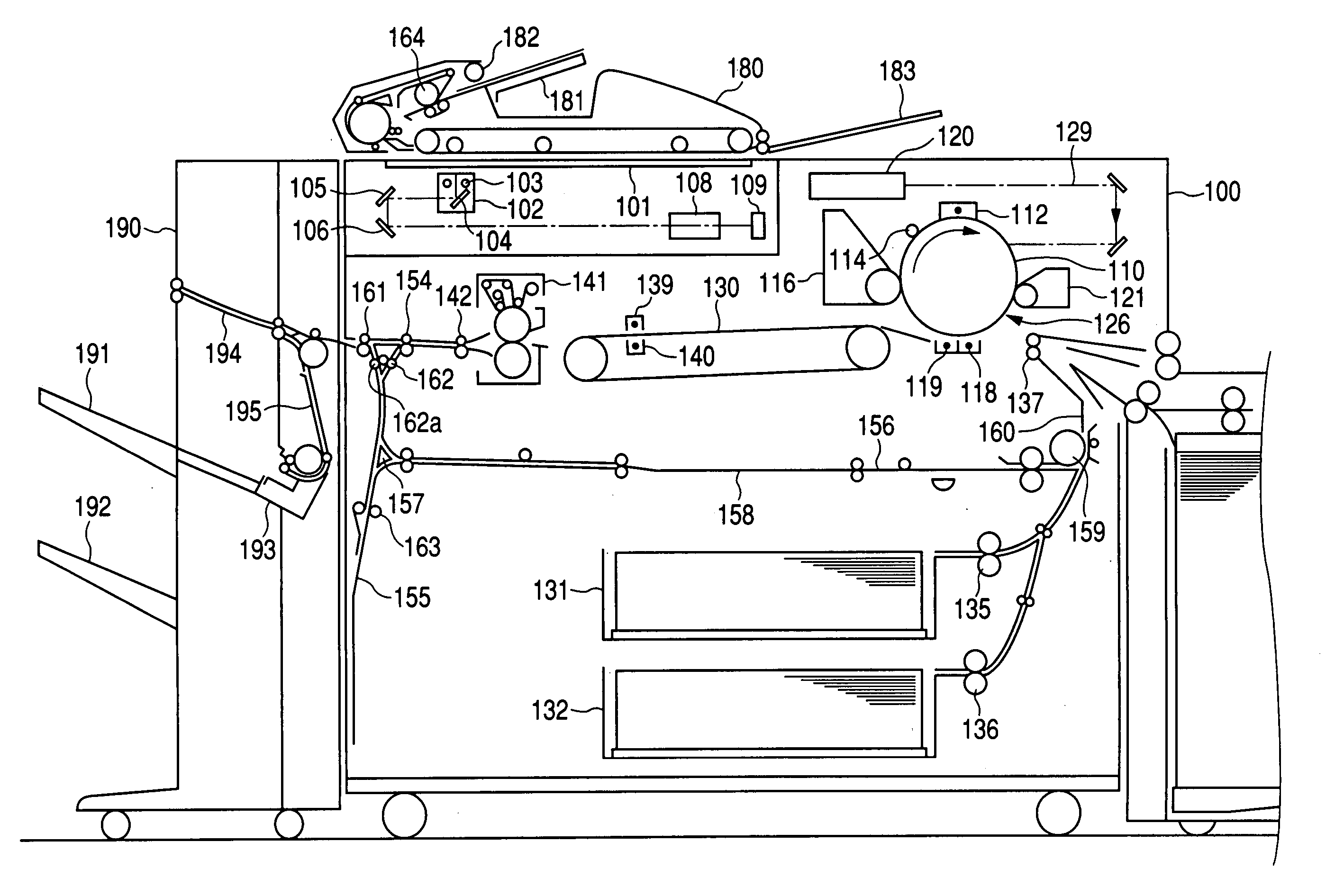
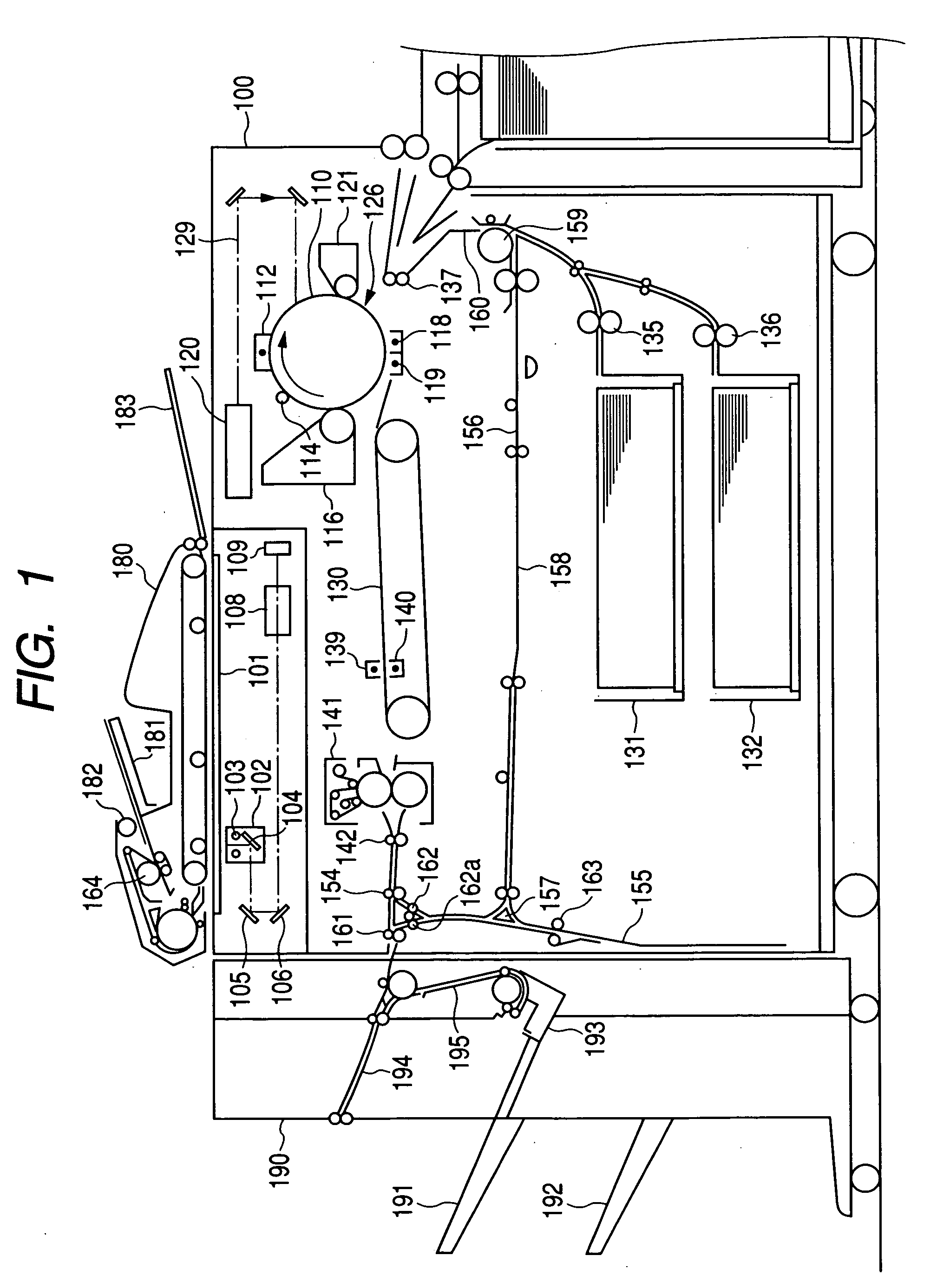
[0045]FIG. 1 is a cross-sectional view showing the construction of an image forming apparatus on which is carried an air feeding unit according to an embodiment of the sheet feeding apparatus of the present invention.

[0046] In FIG. 1, the reference numeral 100 designates an image forming apparatus main body. The reference numeral 101 denotes platen glass (original plate) as an original placing stand. The reference numeral 102 designa...


PUM


Abstract

A sheet feeding apparatus provided with a fan for blowing air against sheets stacked on a sheet tray, a position detecting sensor for detecting the position of the sheets floated up by the fan, and a tray lifting and lowering mechanism for lifting and lowering the sheet tray. The tray lifting and lowering mechanism is controlled on the basis of a result of detection by the position detecting sensor.

Description

BACKGROUND OF THE INVENTION [0001] 1. Field of the Invention [0002] The invention relates to a sheet feeding apparatus for and a sheet feeding method of feeding a sheet to a predetermined position, and a control program for executing a controlling method for the sheet feeding apparatus. [0003] 2. Related Background Art [0004] An image forming apparatus such as a color copying machine or a color printer has heretofore been provided with a sheet feeding apparatus for feeding a sheet cut into a predetermined size to a transferring position in order to transfer a toner image formed on a photosensitive member onto the sheet at the transferring position. [0005] As the sheet feeding apparatus, besides one utilizing a frictional roller, there is also, for example, one which air feeds sheets stacked on a stacking tray (see Japanese Patent Application Laid-Open No. S60-082537). According to this apparatus, for example, in order to effect sheet feeding, air is blown against the uppermost porti...

Claims


Application Information

Patent Timeline
Patent Type & Authority Applications(United States)
IPC IPC(8): B65H3/12B65H3/14B65H1/14B65H3/48B65H29/24B65H31/10
CPCB65H29/246B65H31/10B65H2511/152B65H2511/182B65H2511/20B65H2220/01B65H2220/02B65H2511/18B65H2511/15
Inventor SASAKI, ICHIROISEMURA, KEIZOSATO, MITSUHIKONAGATA, NAOHISANISHIKATA, AKINOBUSUNADA, HIDENORI
Owner CANON KK
Why Eureka
Try Eureka