Conveyer and image recording apparatus

a technology of image recording and conveying machine, which is applied in the direction of thin material processing, printing, article separation, etc., can solve the problems of reducing processing capacity per unit time, affecting the quality of photo prints, and skewing of cutting sheets of photosensitive materials during conveying. , to achieve the effect of short tim

Inactive Publication Date: 2005-09-22
FUJIFILM HLDG CORP +1
View PDF5 Cites 29 Cited by
  • Summary
  • Abstract
  • Description
  • Claims
  • Application Information

AI Technical Summary

Benefits of technology

[0007] In view of the foregoing problems, an object of the present invention is to provide a conveyer that can correct the skew of sheets conveyed in parallel lines in a short time and without fail.

Problems solved by technology

However the cut-sheet of photosensitive material often skews during being conveyed because of mounting tolerance of units in the photo printer and tolerance of parts of individual units.
Especially because the photo print is often output as a white-rimmed print where the recorded image is surrounded with a white rim of a given width, the image recorded on the skew extremely degrades the quality of the photo print.
As a result, the processing capacity per unit time goes down.

Method used


Image

  • Conveyer and image recording apparatus
  • Conveyer and image recording apparatus
  • Conveyer and image recording apparatus

Examples


second embodiment

[0073] Now the second embodiment that apposes conveyer roller pairs will be explained.

[0074] As shown in FIG. 10, a skew corrector 60 has basically the same structure as the skew corrector 19 except that two conveyer roller pairs 61 and 62 are apposed to convey recording sheets 28a and 28b separately. The explanation on the same or equivalent members will be omitted, designating them by the same numbers as the above embodiment. Furthermore, transport guides 37 and 38, a guide shift mechanism 50, a system controller 55, a paper data memory 58, a control panel 59 and other equivalent members are omitted from FIG. 10.

[0075] Capstan rollers 61a and 62a of the conveyer roller pairs 61 and 62 are rotated by feed motors 64a and 64b respectively. And nip rollers 61b and 62b of the conveyer roller pairs 61 and 62 are respectively connected to not-shown shift mechanisms, so that the nip rollers 61b and 62b are individually movable between the nip position and release position in the same way...

first embodiment

[0085] For example, as shown in FIGS. 13A and 13B, instead of the first conveyer roller pair 35 used in the first embodiment shown FIG. 2, it is possible to use a movable nip member 65. The movable nip member 65 consist of a bearing member 65a to support recording sheets 28a and 28b from their backsides (downside in the drawing) and a nipping member 65b which can nip the recording sheets 28a and 28b with the bearing member 65a. The nipping member 65b is movable between a nip position to nip the recording sheets 28a and 28b and a retreat position to retreat upward from the nip position in the drawing. The movable nip member 65 is also movable in parallel to the transport direction of the recording sheets 28 while nipping the recording sheets 28a and 28b. Therefore, it is possible to gain the same effect as using the first conveyer roller pair 35 by moving the movable nip member 65 nipping the recording sheets 28a and 28b by the largest necessary transport amount among those calculate...


PUM

PropertyMeasurementUnit
widthsaaaaaaaaaa
speedsaaaaaaaaaa
transport speedaaaaaaaaaa

Abstract

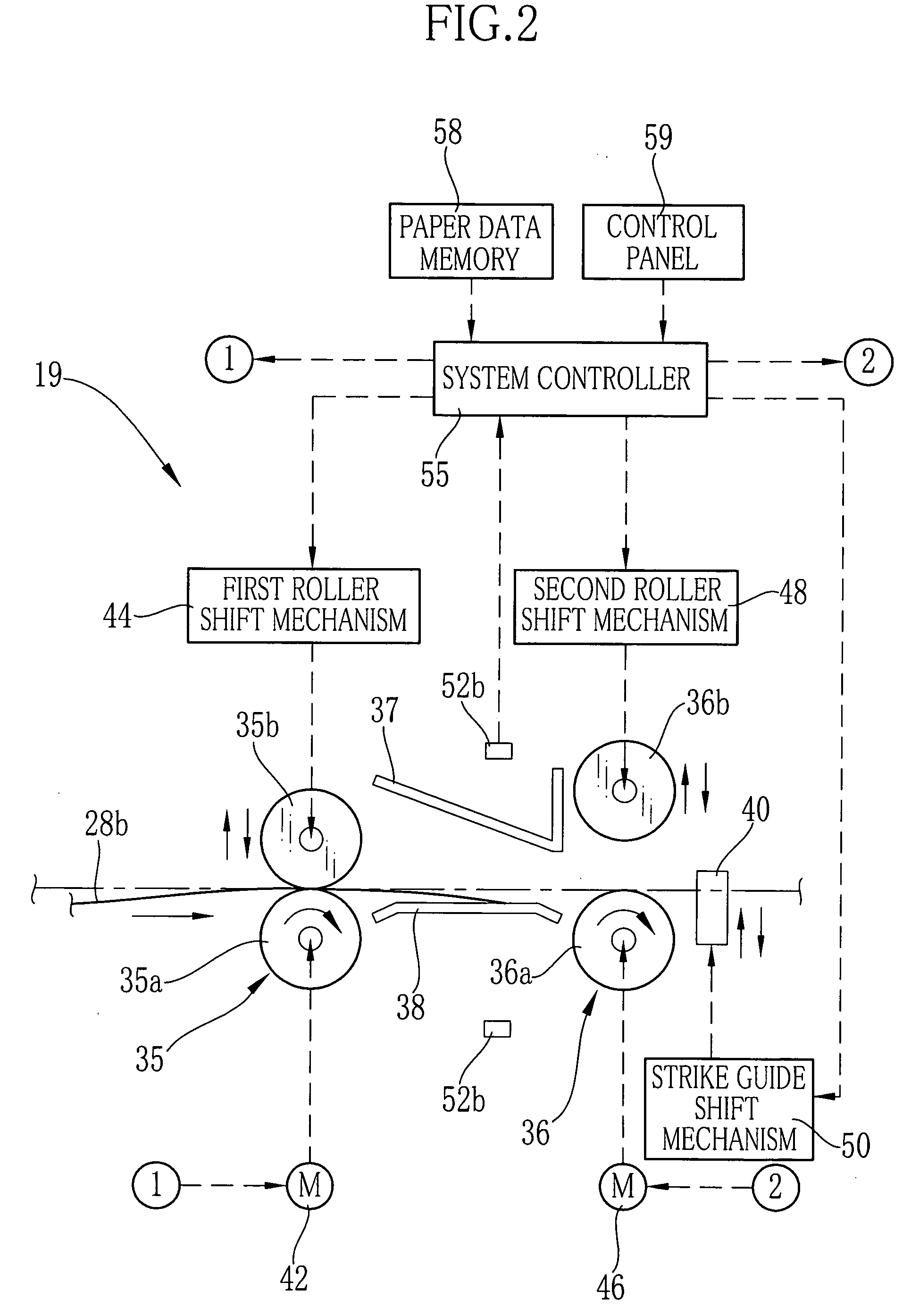
On a paper path in a photo printer, a skew corrector is provided to correct skew of recording sheets simultaneously in two lines. The skew corrector consists of a first conveyer roller pair, a second conveyer roller pair and a strike guide. The recording sheets are conveyed by the first conveyer roller pair after their leading edges strike on the strike guide, to bend the recording sheets flexibly between the first conveyer roller pair and the strike guide, thereby to correct skew of each recording sheet. A necessary transport amount for correcting the skew of the recording sheet is calculated on each line based on detection signals from photo sensors, which are disposed between the first and second conveyer roller pairs, and a width of the recording sheet. The recording sheets of the respective lines are conveyed by the largest necessary transport amount among the calculated ones.

Description

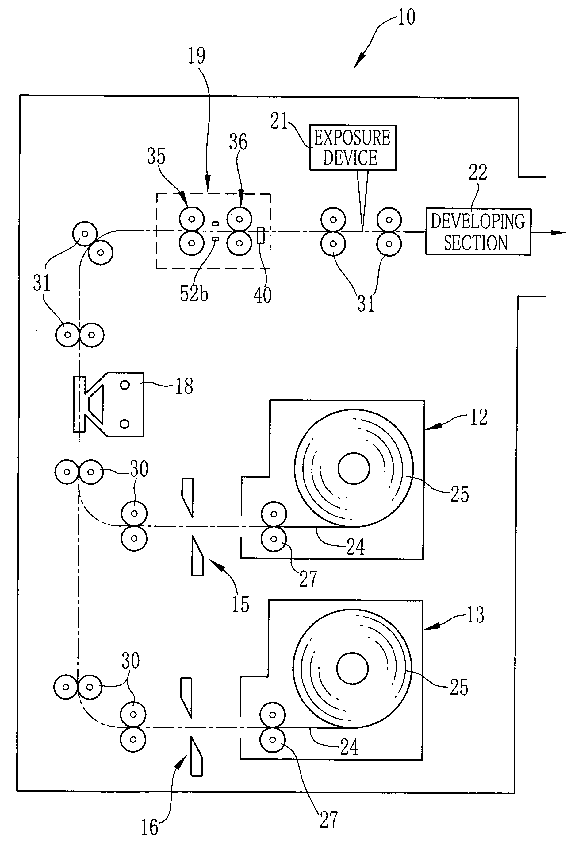
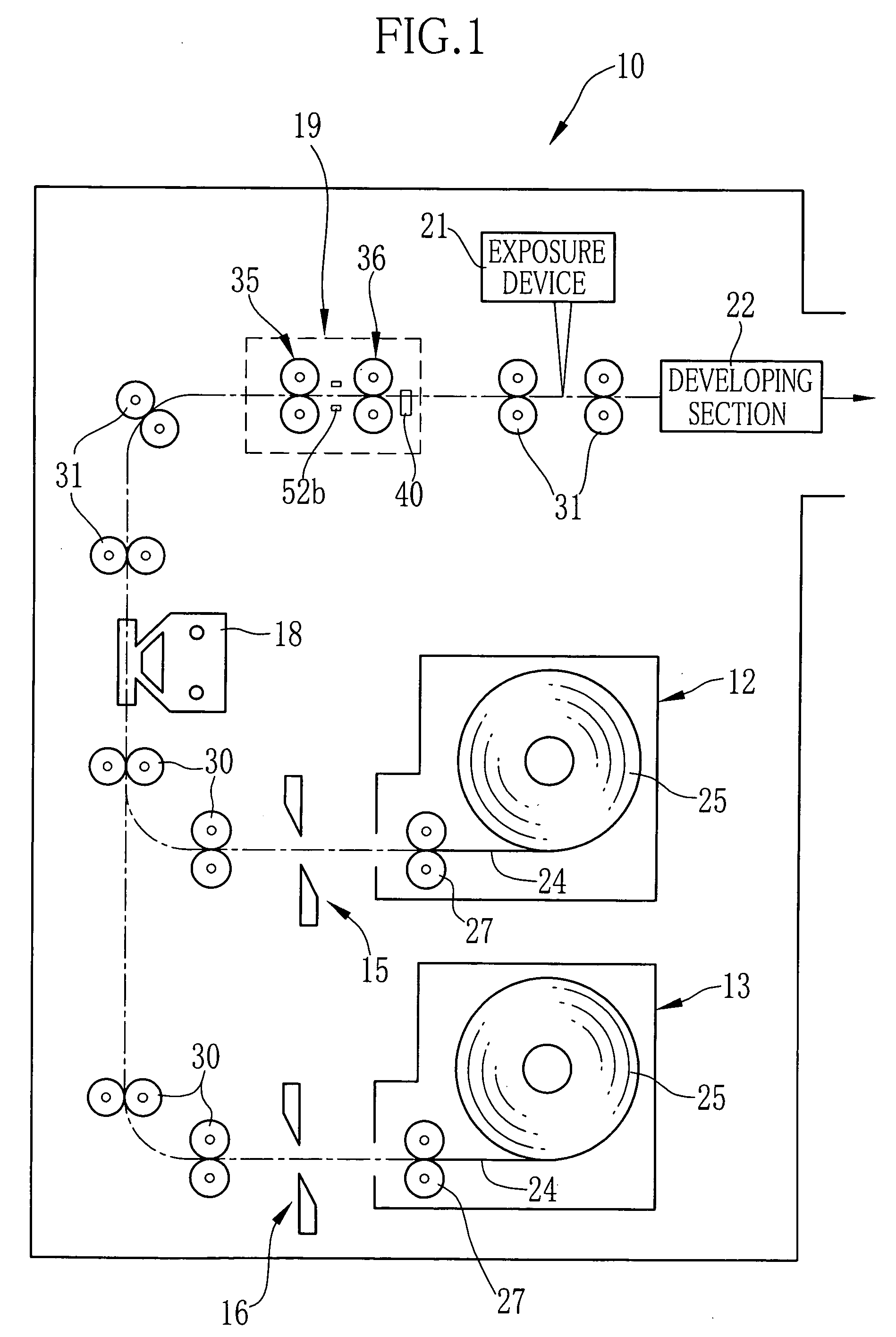
FIELD OF THE INVENTION [0001] The present invention relates to a conveyer that conveys sheets in parallel lines and to an image recording apparatus that records an image on a sheet of recording material conveyed by the conveyer. BACKGROUND ART [0002] For example, a photo printer records an image by so-called scanning exposure that scans recording light in a main scan direction perpendicular to a sub scan direction while nipping and conveying a cut-sheet of photosensitive material in the sub scan direction by plural pairs of conveyer rollers provided on a paper path. [0003] In order to obtain a high-quality photo print, it is necessary that the photosensitive material is exposed in an appropriate position and direction. However the cut-sheet of photosensitive material often skews during being conveyed because of mounting tolerance of units in the photo printer and tolerance of parts of individual units. When the photosensitive material on the skew is exposed, the recorded image is al...

Claims


Application Information

Patent Timeline
Patent Type & Authority Applications(United States)
IPC IPC(8): B41J11/42B41J2/44B65H5/00B65H5/06B65H9/00
CPCB65H5/062B65H9/004B65H9/06B65H2301/121B65H2301/331B65H2404/1441B65H2701/1719B65H2701/1313B65H2220/03B65H2220/01
Inventor TANABE, TSUYOSHI
Owner FUJIFILM HLDG CORP
Why Eureka
Try Eureka