Stator for an electric motor

a technology for electric motors and stator windings, which is applied in the direction of windings, magnetic circuit rotating parts, magnetic circuit shapes/forms/constructions, etc., can solve the problem that the space available for stator windings cannot be fully exploited

Inactive Publication Date: 2005-09-22
MINEBEA CO LTD
View PDF12 Cites 11 Cited by
  • Summary
  • Abstract
  • Description
  • Claims
  • Application Information

AI Technical Summary

Benefits of technology

[0016] Thus according to the invention, a stator is provided in which the stator windings do not only lie next to each other in the direction of the circumference as is commonly the case, but in which the radial dimension of the stator is additionally exploited and the windings of several phases are arranged one on top of the other in selected deeper stator slots. The design of the stator according to the invention goes to increase the copper space of the stator slots, resulting in an improved space factor and improved exploitation of the electric motor. In a three-phase electric motor having a nine-slot stator it is possible, for example, to increase the number of winding portions from three to four by providing a deeper stator slot per phase. If for each phase of the electric motor, a deeper stator slot is provided, it generally applies that for an electric motor having x phases and a stator body having y slots, for each phase of the electric motor (yx)+1 windings can be provided.
[0018] The design of the stator slots according to the invention makes it possible to use prefabricated coils as stator windings which are simply slid over the stator teeth from the slot opening, or to easily insert the windings into the stator slots since, at their open ends, the openings of these stator slots are not constricted as is commonly the case in the prior art.
[0020] According to the invention, provision can further be made for the stator core to have other recesses separate from the stator slots. These recesses are used, on the one hand, to reduce the weight of the stator core, but can also be used as channels to ventilate the stator core for improved thermal conductivity.

Problems solved by technology

Accordingly, this means that the space available for the stator winding cannot be fully exploited.

Method used


Image

  • Stator for an electric motor
  • Stator for an electric motor
  • Stator for an electric motor

Examples


Embodiment Construction

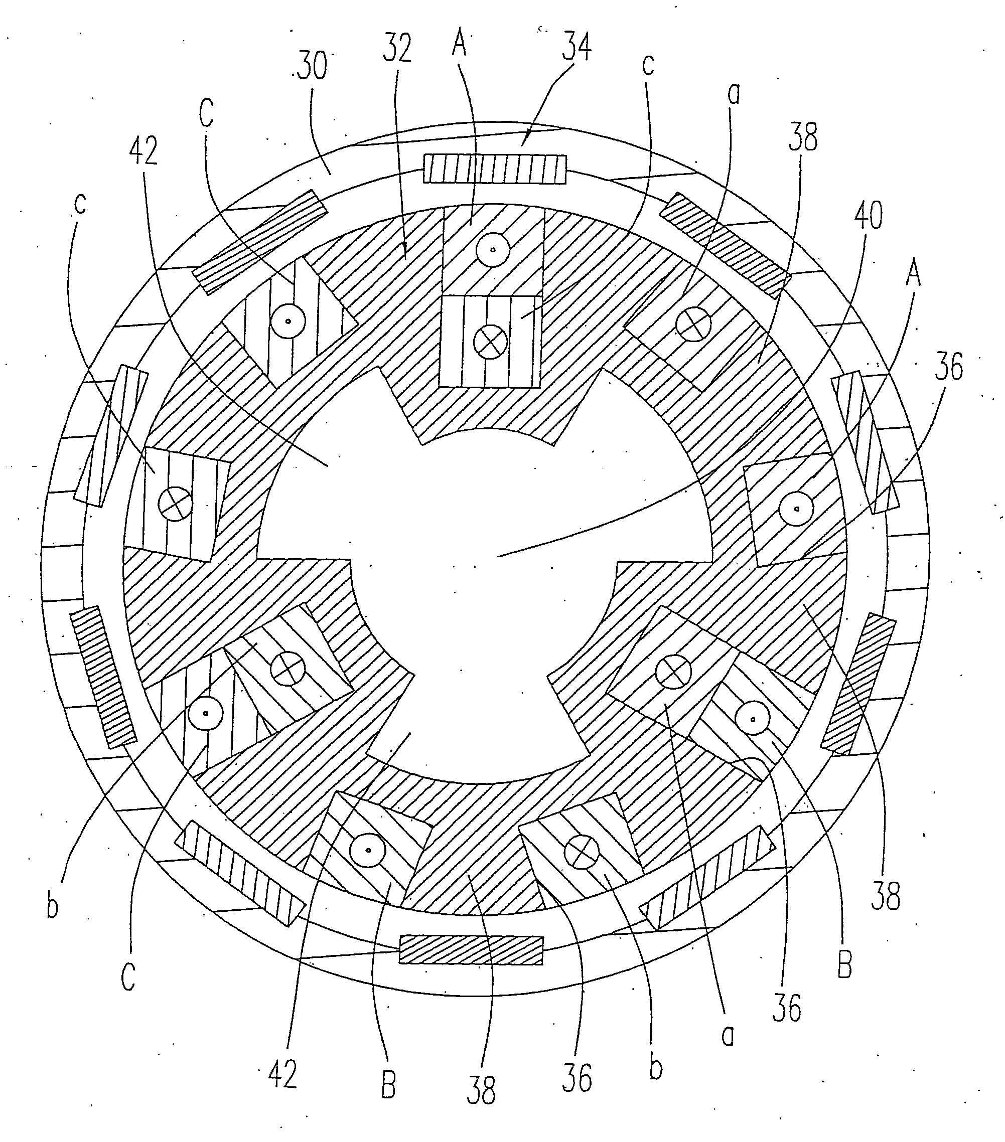
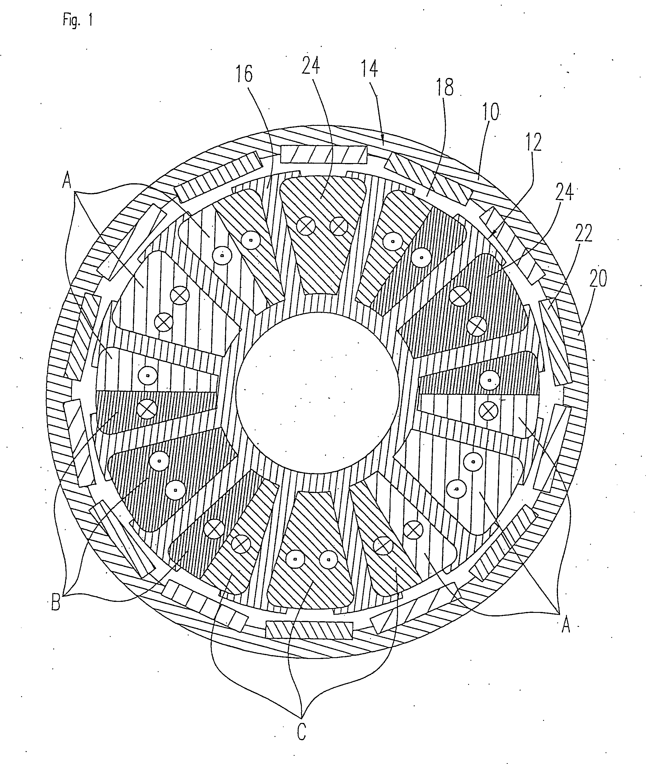
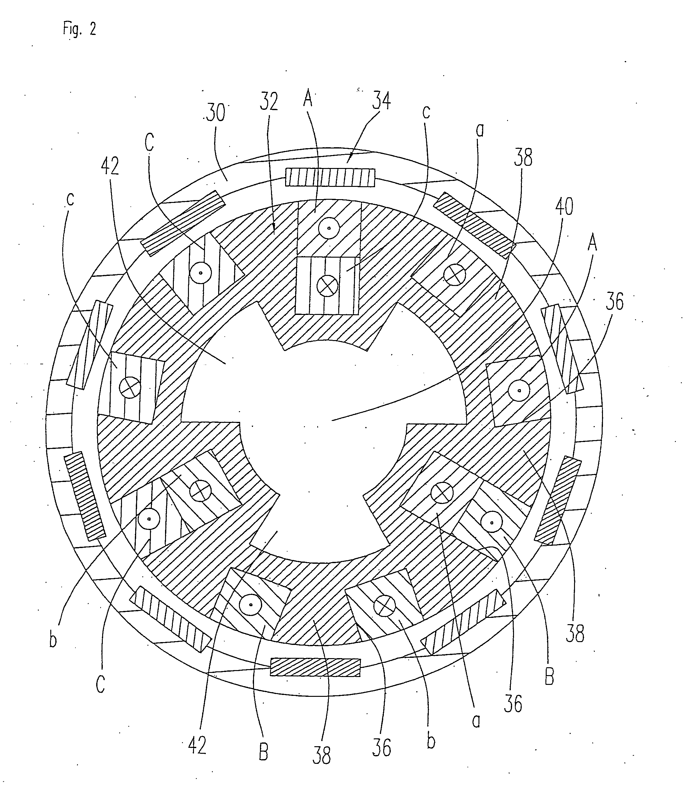
[0026] The electric motor illustrated in FIG. 2 comprises a housing 30 in which a stator arrangement 32 and a rotor arrangement 34 are accommodated. The basic component of the stator arrangement is a stator body having a stator core or stator back yoke which can be made up, for example, of stacked iron laminations or pressed from iron powder. The rotor arrangement 34 can essentially be constructed as described in reference to FIG. 1 and is not gone into in more detail again here.

[0027] The stator arrangement has stator slots 36 and stator teeth 38. As shown in FIG. 2, the stator slots can extend in a radial direction into the stator core to different depths. The side walls of each stator slot 36 are arranged essentially parallel to each other. The stator slots 36 with parallel side walls go to produce stator teeth 38 which widen towards the outer circumference of the stator arrangement 32 which has a beneficial effect on the flow transfer behavior between the stator arrangement 32 ...


PUM


Abstract

A stator for an electric motor having a stator core which has a number of stator teeth and stator slots located between the stator teeth, the stator slots being designed to receive stator windings, the stator slots being given different depths in order to accommodate the portions of the stator windings of one phase or several phases of the electric motor respectively.

Description

FIELD OF THE INVENTION [0001] The invention relates to a stator for an electric motor having a stator core which has a number of stator teeth and stator slots located between the stator teeth, the stator slots being designed to receive stator windings. BACKGROUND OF THE INVENTION [0002] More generally, the invention relates to the field of electric motors having permanent magnets such as brushless, electronically commutated DC motors and other permanent magnet motors, the motor according to the invention being configured as either an inner rotor motor or an outer rotor motor. In general, inner rotor motors consist of a rotor arrangement which is mounted onto a motor shaft and includes one or more permanent magnets, as well as a stator arrangement having a stator core which is constructed, for example, from metal laminations and carries windings. [0003] In the case of inner rotor motors, the rotor arrangement is coaxially inserted into the stator arrangement and rotatably journaled w...

Claims


Application Information

Patent Timeline
Patent Type & Authority Applications(United States)
IPC IPC(8): H02K1/00H02K1/16H02K1/20H02K3/12H02K17/00H02K21/16H02K21/22
CPCH02K1/16H02K3/12H02K1/20H02K1/165
Inventor HANS, HELMUT
Owner MINEBEA CO LTD
Why Eureka
Try Eureka