Thermal module with heat reservoir and method of applying the same on electronic products

a technology of heat reservoir and thermal module, which is applied in the direction of cooling/ventilation/heating modification, semiconductor/solid-state device details, semiconductor devices, etc., can solve the problems of insufficient high-speed ic chips, limited maximum heat dissipation capability, and current thermal modules available on the market can not meet the challenge, so as to reduce the overall power consumption of electronic products and ensure the stability of the same

Inactive Publication Date: 2005-09-22
IND TECH RES INST
View PDF13 Cites 77 Cited by
  • Summary
  • Abstract
  • Description
  • Claims
  • Application Information

AI Technical Summary

Benefits of technology

[0013] The second object of the invention is to provide a thermal module with heat reservoir and method of applying the same on electronic products, which is capable of reducing the power consumed by the same and thus reducing the overall power consumption of the electronic product.
[0014] It is another object of the invention to provide a thermal module with heat reservoir and method of applying the same on electronic products, which is capable of ensuring the stability of the same during heat dissipating and thus ensuring the durability and reliability of the IC chip.
[0015] Yet, another object of the invention is to provide a thermal module with heat reservoir and method of applying the same on electronic products, which is capable of integrating and cooperating with other heat dissipating devices so as to increase the design flexibility of the same.

Problems solved by technology

However, facing the ICs of next generation, current thermal modules available on the market can not meet the challenge.
The maximum heat dissipating capability is limited that it is insufficient for high-speed IC chips.
The selection and combination of the thermal module design is limited such that the design of the electronic products applying the same is also limited.
The power consumed by the conventional thermal module is relatively huge.
The instability of the conventional thermal module during heat dissipating will severely shorten the durability and reliability of the IC chip.
The design flexibility of the conventional thermal module is limited since it cannot integrate and cooperate in other applications.

Method used


Image

  • Thermal module with heat reservoir and method of applying the same on electronic products
  • Thermal module with heat reservoir and method of applying the same on electronic products
  • Thermal module with heat reservoir and method of applying the same on electronic products

Examples


Embodiment Construction

[0035] For your esteemed members of reviewing committee to further understand and recognize the fulfilled functions and structural characteristics of the invention, several preferable embodiments cooperating with detailed description are presented as the follows.

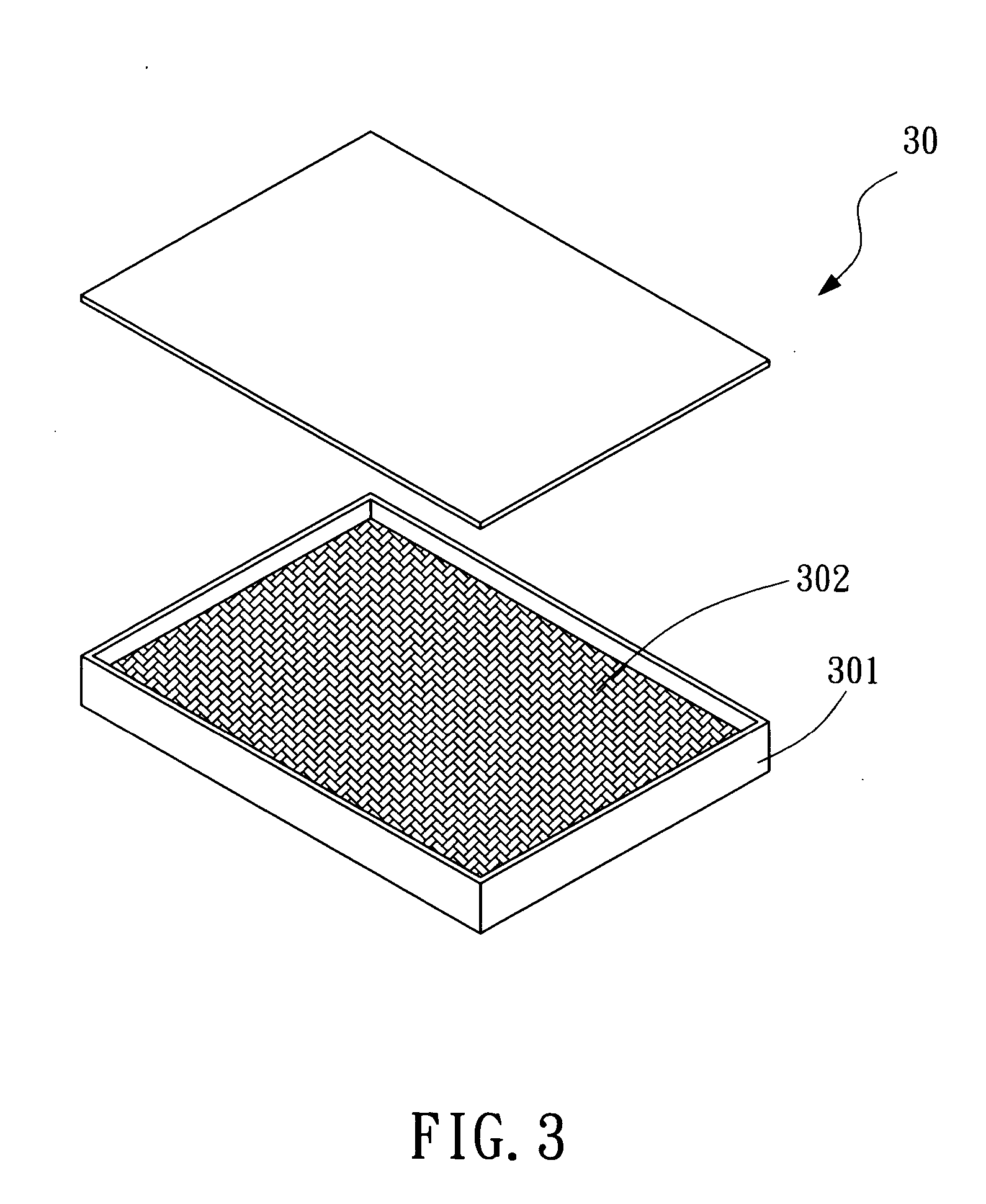
[0036] Please refer to FIG. 3, which is an exploded diagram showing a heat absorber 30 according to a preferred embodiment of the present invention. The heat absorber 30 of the invention uses an isothermal process of a material stored therein to absorb heat. The heat absorber 30 is an airtight structure consisted of a housing 301 and a phase change material. The housing 301 is made of a material of high heat conductivity that is not reacting with the phase change material 302. The phase change material 302 is disposed within the housing 301, and is capable of changing from a first state to a second state by absorbing heat and changing from the second state to the first state by releasing the heat stored therein.

[0037] The ...


PUM


Abstract

The present invention discloses a thermal module with heat reservoir, which is arranged with respect to a chip, and the thermal module comprises: a housing, disposed at a appropriate position corresponding to the chip and made of a material of high heat conductivity; a phase change material, disposed within the housing, capable of changing from a first state to a second state by absorbing heat and changing from the second state to the first state by releasing the heat stored therein; wherein the thermal module can be either mounted on the chip at an appropriate location or disposed at a location separated from the chip by an appropriate distance, in addition, the phase change process of the phase change material changing between the first state and the second state can be either a physical process or a chemical process.

Description

FIELD OF THE INVENTION [0001] The present invention relates to a thermal module with heat reservoir and method of applying the same on electronic products, and more particularly, to a thermal module with heat reservoir capable of transforming heat generated by an integrated circuit (IC) into latent heat stored in the heat reservoir for enabling the IC to keep a constant working temperature, such that the electronic products using the thermal module not only have a better heat dissipating capability, but also have a better operating stability since it is able to avoid the damage or break down caused by an abrupt temperature raising of power burst. BACKGROUND OF THE INVENTION: [0002] With rapid advance of communication technology, there are increasing demands for high performance integrated circuit such as microprocessors. However, the better performance the IC is, the more heat it will generate, and the heat generated by the IC must be removed to insure that the working temperature t...

Claims


Application Information

Patent Timeline
Patent Type & Authority Applications(United States)
IPC IPC(8): H05K7/20
CPCH01L23/427H01L2924/0002H01L2924/00
Inventor TSENG, MING-HSICHIEN, HENG-CHIEHWANG, CHIH-YAO
Owner IND TECH RES INST
Why Eureka
Try Eureka