Road milling machine with optimized operation
- Summary
- Abstract
- Description
- Claims
- Application Information
AI Technical Summary
Benefits of technology
Problems solved by technology
Method used
Image
Examples
Embodiment Construction
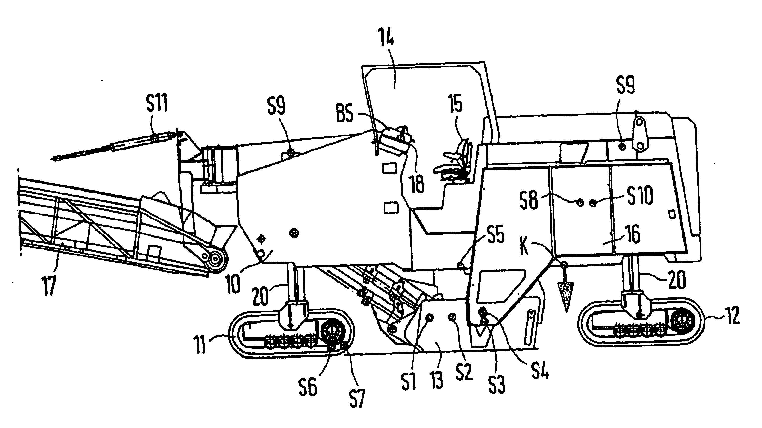
[0040] The lateral view of a road milling machine shows the basic structure and the components of the machine. A machine frame 10 is the basis for the machine, and is supported by two front running gears 11 and two rear running gears 12. In this case, the running gears 10 and 11 can be driven by electric motors or hydraulic motors. These drive mechanisms operate synchronously. It is thus sufficient to assign sensors S6 and S7 for detecting the electrical current or the pressure and the speed to only one running gear, for example 11.
[0041] A milling box 13 is attached to the machine frame 10 between the front and rear running gears 11 and 12. The milling box 13 contains at least one milling roller with chisel holders and chisels. The milling roller is driven by a drive unit 16, which has a Diesel engine, wherein a sensor S8 detects the transferred torque, and a sensor S10 detects other operating data, such as motor rpm, exhaust gas temperature, boost pressure, and the like.
[0042] A...
PUM
| Property | Measurement | Unit |
|---|---|---|
| Force | aaaaa | aaaaa |
| Power consumption | aaaaa | aaaaa |
| Torque | aaaaa | aaaaa |
Abstract
Description
Claims
Application Information
 - R&D
- Intellectual Property
- Life Sciences
- Materials
- Tech Scout
- Unparalleled Data Quality
- Higher Quality Content
- 60% Fewer Hallucinations
Browse by: Latest US Patents, China's latest patents, Technical Efficacy Thesaurus, Application Domain, Technology Topic, Popular Technical Reports.
© 2025 PatSnap. All rights reserved.Legal|Privacy policy|Modern Slavery Act Transparency Statement|Sitemap|About US| Contact US: help@patsnap.com


