
Machine for removing sump pit water and process for making same

a technology of sump pit and machine, which is applied in the field of sump ejector, can solve the problems of lack of long-term pumping capacity, flood of the base area, and common use of battery back-up pumps, so as to reduce pumping rates, prevent backflow, and eliminate back pressure

Inactive Publication Date: 2005-09-22
BONIFACIO WILLIAM JAMES +1
View PDF1 Cites 11 Cited by
  • Summary
  • Abstract
  • Description
  • Claims
  • Application Information

AI Technical Summary

Benefits of technology

[0015] Another object of the invention is to provide a sump ejector system that can be pressurized without damage.
[0017] In accordance with a preferred embodiment of the invention, there is disclosed a machine for removing sump pit water comprising: sump ejector mounted at the same elevation as the discharge pipe, eliminating back pressure which reduces pumping rates, sump ejector system with an adjustable control allowing the pump to run for various lengths of time, an independent discharge line, sump ejector with an independent suction line, sump ejector with an internal check valve, sump ejector with an atmospheric vent preventing backflow, and sump ejector with integral backflow prevention device.
[0018] In accordance with a preferred embodiment of the invention, there is disclosed a process for removing sump pit water comprising the steps of: sump ejector mounted at the same elevation as the discharge pipe, eliminating back pressure which reduces pumping rates, sump ejector system with an adjustable control allowing the pump to run for various lengths of time, an independent discharge line, sump ejector with an independent suction line, sump ejector with an internal check valve, sump ejector with an atmospheric vent preventing backflow, and sump ejector with integral backflow prevention device.

Problems solved by technology

In the case of power failures the electric operated pump does not operate hence the basement area floods.
Battery back-up pumps are commonly used in these applications but lack sufficient capacity to pump for long durations.
This allows the development of corrosion and mineral deposits to form on the working parts, which cause mechanical failures.
In addition, the placement of the ejector pump into the sump pit creates space interference problems in relationship to the primary pump.
The prior technology of the water-powered pump is deficient in that the ejectors are located inside the sump pit and submersed under water.
The ejectors may corrode and / or form mineral deposits on them, hence affecting the operation of the pump.
The ejectors located inside the sump pit are difficult to install due to the fact that space is limited in relationship to the main pump also inside.
When the ejectors are mounted inside the pit, it requires that the sump water be pumped upward creating a backpressure, which greatly reduces the pumping volume.
The prior technology of the battery powered pump is deficient in the same manner as the water powered pump being located inside the pit, but also having limited pumping capacity depending on battery condition.
The owner is required to monitor and change out heavy, dangerous, and expensive batteries.

Method used


Image

  • Machine for removing sump pit water and process for making same
  • Machine for removing sump pit water and process for making same
  • Machine for removing sump pit water and process for making same

Examples


Embodiment Construction

[0023] Detailed descriptions of the preferred embodiment are provided herein. It is to be understood, however, that the present invention may be embodied in various forms. Therefore, specific details disclosed herein are not to be interpreted as limiting, but rather as a basis for the claims and as a representative basis for teaching one skilled in the art to employ the present invention in virtually any appropriately detailed system, structure or manner.

DETAILED DESCRIPTION OF THE INVENTION

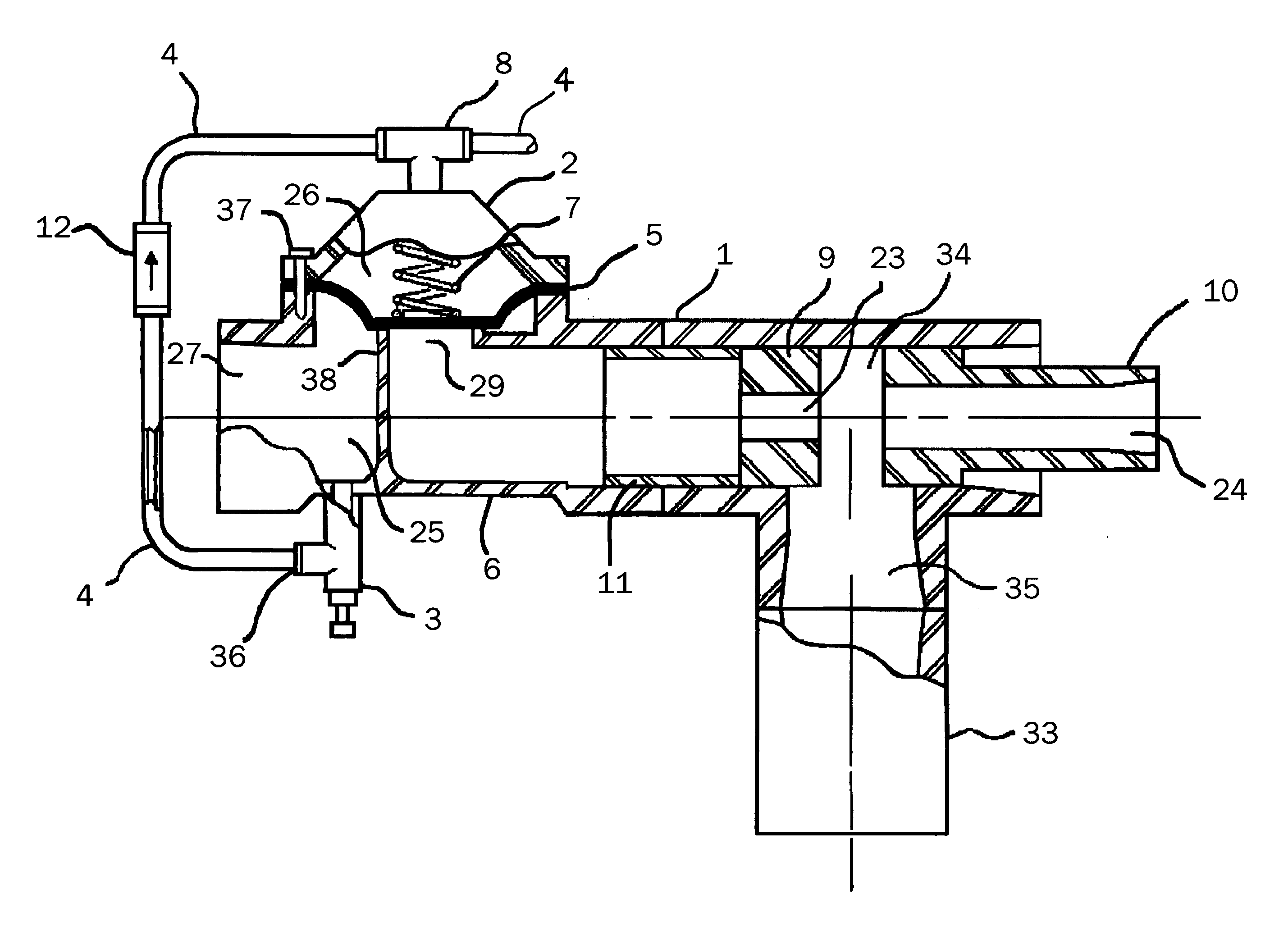
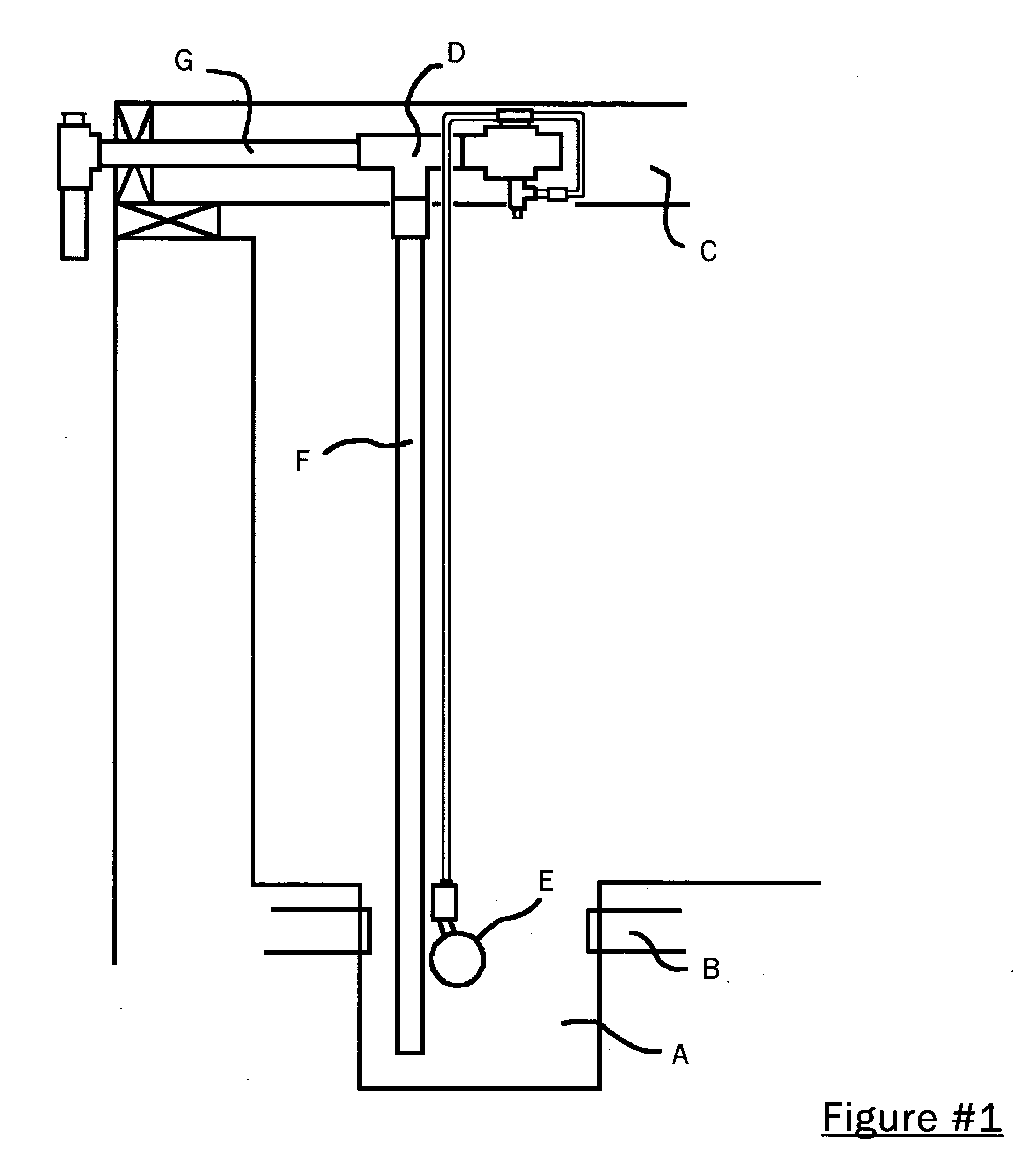
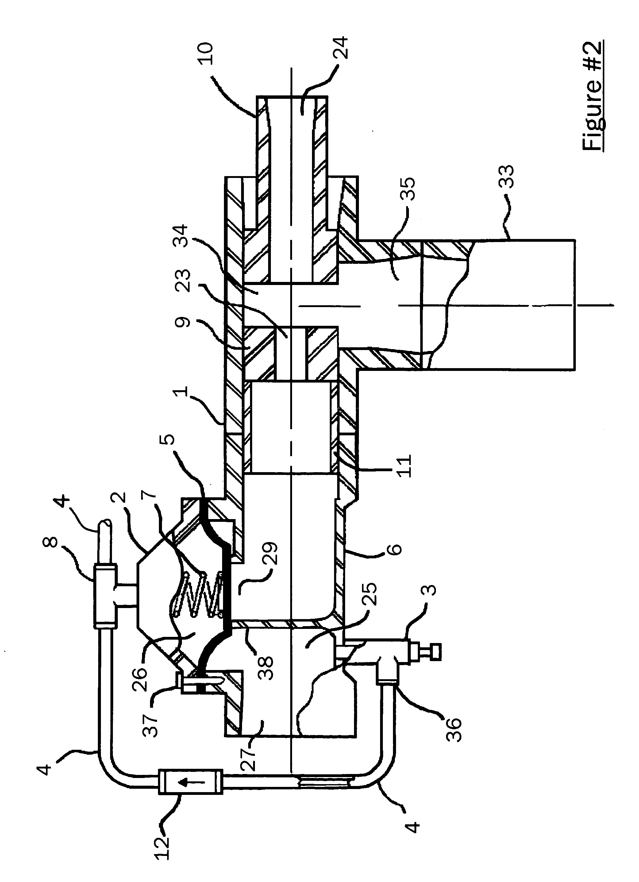
[0024] Referring to the drawing and more particularly to FIG. 1, reference letter-“A” indicates a sump pit having water inlet pipes as shown by letter-“B”. An ejector valve mounted to the basement ceiling rafters letter-“C” as best shown in figure # 1 an ejector valve letter-“D”. The ejector valve as detailed in figure #2 comprising of valve body 6 a valve cover 2 and a solid flexible rubber diaphragm 5. The ejector valve having a lower chamber 25, an upper chamber 26 and being isolated by said...


PUM


Abstract

A machine for removing sump pit water with sump ejector mounted at the same elevation as the discharge pipe, eliminating back pressure which reduces pumping rates, sump ejector system with an adjustable timing control allowing the pump to run for various lengths of time, a independent discharge line, sump ejector with an independent suction line, sump ejector with an internal check valve, sump ejector with an atmospheric vent preventing backflow, and sump ejector with integral backflow prevention device.

Description

STATEMENT REGARDING FEDERALLY SPONSORED RESEARCH OR DEVELOPMENT [0001] Not Applicable DESCRIPTION OF ATTACHED APPENDIX [0002] Not Applicable BACKGROUND OF THE INVENTION [0003] This invention relates generally to the field of basement flooding and more specifically to a machine for removing sump pit water and process for making same. The use of a sump pump in the basement of a residential or commercial building is standard equipment to avoid flooding. Electrical driven motor pumps are used standard as primary pumps and operate with the rising and lowering of sump ground water levels. In the case of power failures the electric operated pump does not operate hence the basement area floods. [0004] Battery back-up pumps are commonly used in these applications but lack sufficient capacity to pump for long durations. Water powered pumps provide unlimited pumping time providing city water pressure is available. However, water powered pumps as shown in U.S. Pat. No. 5,302,088 & U.S. Pat. No....

Claims


Application Information

Patent Timeline
IPC IPC(8): E03F5/22F04B17/00F04F5/46F04F5/48
CPCE03F5/22F04F5/48F04F5/461
Inventor BONIFACIO, WILLIAM JAMESBELLE, JAMES DOMINIC
Owner BONIFACIO WILLIAM JAMES
Learn More