
Exhaust system for an internal combustion engine and method for controlling the exhaust system

a technology of exhaust system and internal combustion engine, which is applied in the direction of electrical control, exhaust treatment electric control, separation process, etc., can solve the problems of reducing performance at full load, adversely affecting the efficiency of the doc, etc., to reduce the back pressure of the pre-turbine diesel oxidation catalyst, and avoid adverse effects on the efficiency of the turbin

Inactive Publication Date: 2018-08-14
GM GLOBAL TECH OPERATIONS LLC
View PDF10 Cites 0 Cited by
  • Summary
  • Abstract
  • Description
  • Claims
  • Application Information

AI Technical Summary

Benefits of technology

This patent describes a way to improve the performance of a catalyst used in a vehicle's exhaust system. By bypassing a specific part of the system, the catalyst can work at higher temperatures before the turbine, increasing the conversion of harmful gases. This improves the vehicle's emissions control while maintaining the efficiency of the turbine. The bypass also reduces the back pressure from the catalyst, providing further benefits.

Problems solved by technology

In particular, a turbine for a turbocharger will reduce the temperature of the exhaust stream and thus may adversely affect the efficiency of the DOC.
This may result in reduced performance at full load.

Method used


Image

  • Exhaust system for an internal combustion engine and method for controlling the exhaust system
  • Exhaust system for an internal combustion engine and method for controlling the exhaust system
  • Exhaust system for an internal combustion engine and method for controlling the exhaust system

Examples


Embodiment Construction

[0031]Referring to FIG. 3, a schematic illustration of an exemplary embodiment of an exhaust system 300 in accordance with the present disclosure is shown. The exhaust system 300 includes an exhaust stream 302 which flows through the entire exhaust system 300. Those of ordinary skill in the art understand that the exhaust stream may originate from an internal combustion engine (not shown). The exhaust system 300 includes a turbine 304 positioned in the exhaust stream 302, a first diesel oxidation catalyst (DOC) 306 positioned upstream of the turbine 304 in the exhaust stream 302, and a bypass valve 308. The exemplary exhaust system 300 also includes a second diesel oxidation catalyst (DOC) 310 positioned downstream of the turbine 304 in the exhaust stream 302. The bypass valve 308 is operable to selectively cause the exhaust stream 302 to flow through the first DOC 306 or to flow through an alternate / bypass route 312, such that the exhaust stream 302 does not flow through the first ...


PUM


Abstract

An exhaust system for an internal combustion engine for a vehicle includes a turbine positioned in an exhaust stream from the internal combustion engine, a first diesel oxidation catalyst positioned upstream of the turbine within the exhaust stream, and a bypass for selectively bypassing the exhaust stream around the diesel oxidation catalyst to the turbine.

Description

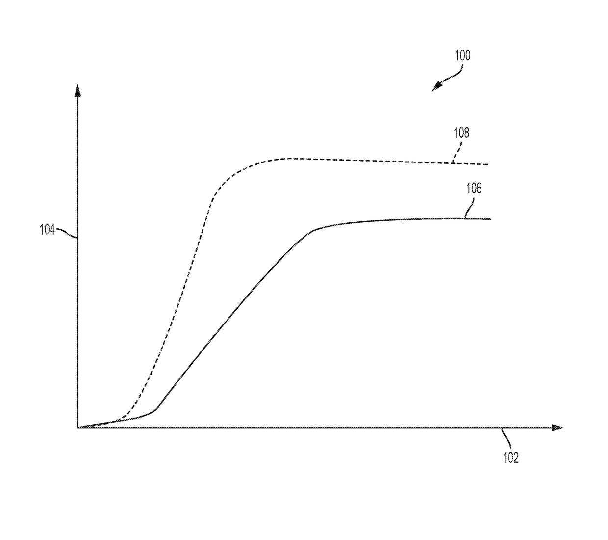
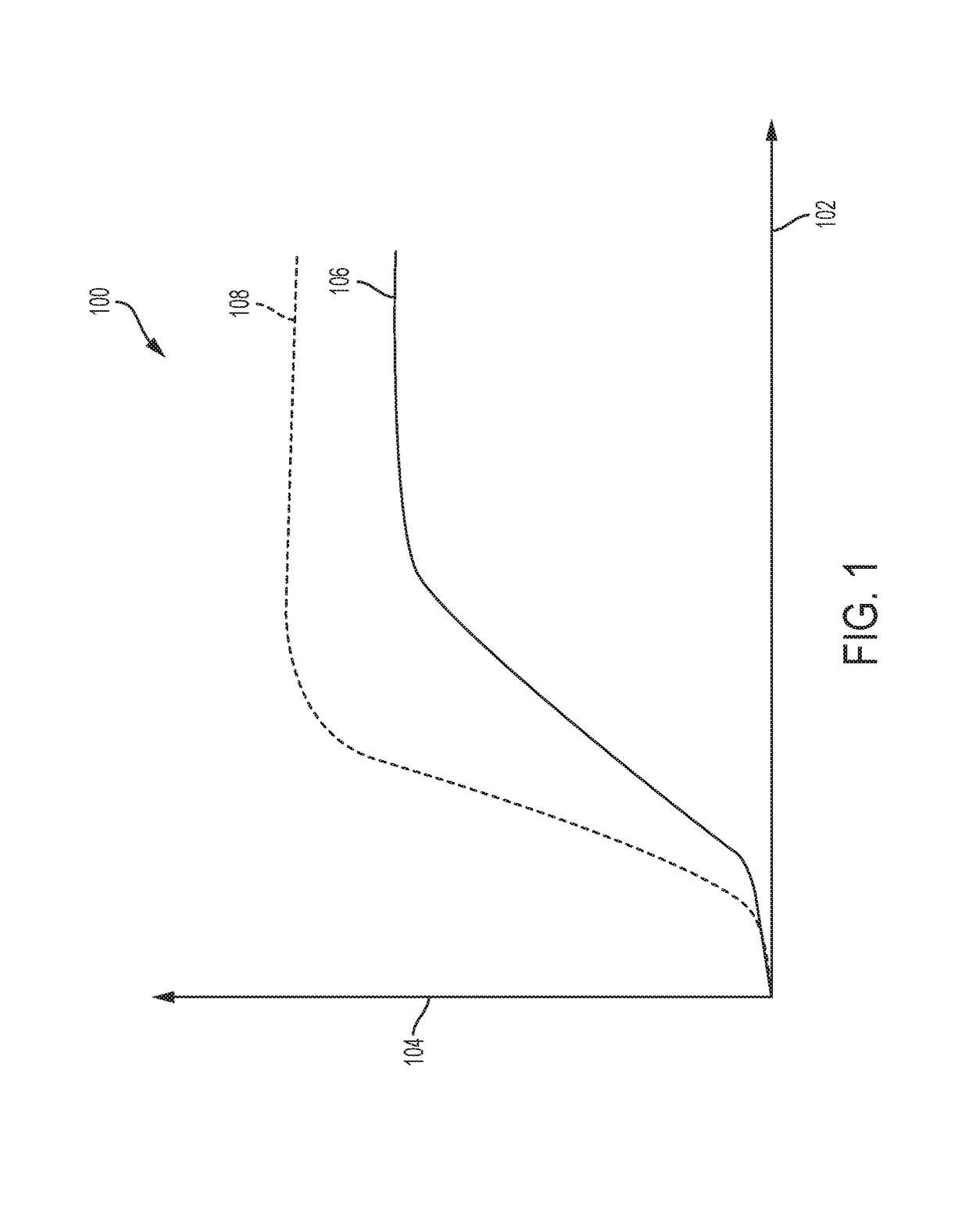
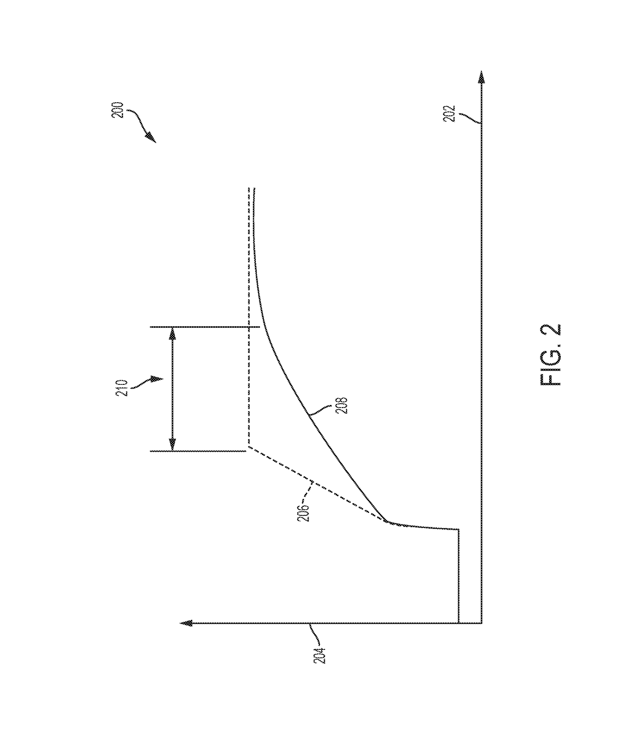
FIELD[0001]The present disclosure relates to an exhaust system for an internal combustion engine and a method for controlling the exhaust system.INTRODUCTION[0002]This introduction generally presents the context of the disclosure. Work of the presently named inventors, to the extent it is described in this introduction, as well as aspects of the description that may not otherwise qualify as prior art at the time of filing, are neither expressly nor impliedly admitted as prior art against this disclosure.[0003]Exhaust systems for an internal combustion system having a turbocharger may also include a diesel oxidation catalyst (DOC) positioned downstream in the exhaust stream from the turbine of the turbocharger. The DOC oxidizes hydrocarbons (HC) and carbon monoxides (CO) into carbon dioxide (CO2) and water (H2O). The effectiveness of a DOC in relation to temperature is generally illustrated in FIG. 1.[0004]FIG. 1 shows a graph 100 with a first axis 102 representing temperature and a ...

Claims


Application Information

Patent Timeline
Patent Type & Authority Patents(United States)
IPC IPC(8): F01N3/20F01N3/10B01D53/94F01N9/00F02B37/02F01N11/00F01N3/28
CPCF01N3/2053B01D53/9495F01N3/103F01N3/2803F01N3/2825F01N9/00F01N11/002F02B37/02B01D53/944F01N2900/1404F01N2340/06F01N2410/00F01N2410/02F01N2900/0414F01N2900/08F01N13/0093F01N2260/06F02D41/0007F02D41/027F02D41/10F02D41/1446F02D41/405Y02A50/20Y02T10/12Y02T10/40
Inventor RICCI, ISADORAMONTINARO, GIOVANNIREYNIER, EMILIEBARIA, RICCARDO
Owner GM GLOBAL TECH OPERATIONS LLC
Learn More