Carriage direction switching apparatus for test-tube carrier path

a technology of carrier path and switching apparatus, which is applied in the direction of packaging foodstuffs, instruments, packaged goods, etc., can solve the problems of testing tube holder b>10/b> being carried, and achieve the effect of avoiding the breakag

Inactive Publication Date: 2005-09-22
IDS CO LTD
View PDF3 Cites 54 Cited by
  • Summary
  • Abstract
  • Description
  • Claims
  • Application Information

AI Technical Summary

Benefits of technology

[0038]FIG. 5 is a plan view illustrating a major part of a conventiona...

Problems solved by technology

As a result, the test-tube holde...

Method used


Image

  • Carriage direction switching apparatus for test-tube carrier path
  • Carriage direction switching apparatus for test-tube carrier path
  • Carriage direction switching apparatus for test-tube carrier path

Examples


first embodiment

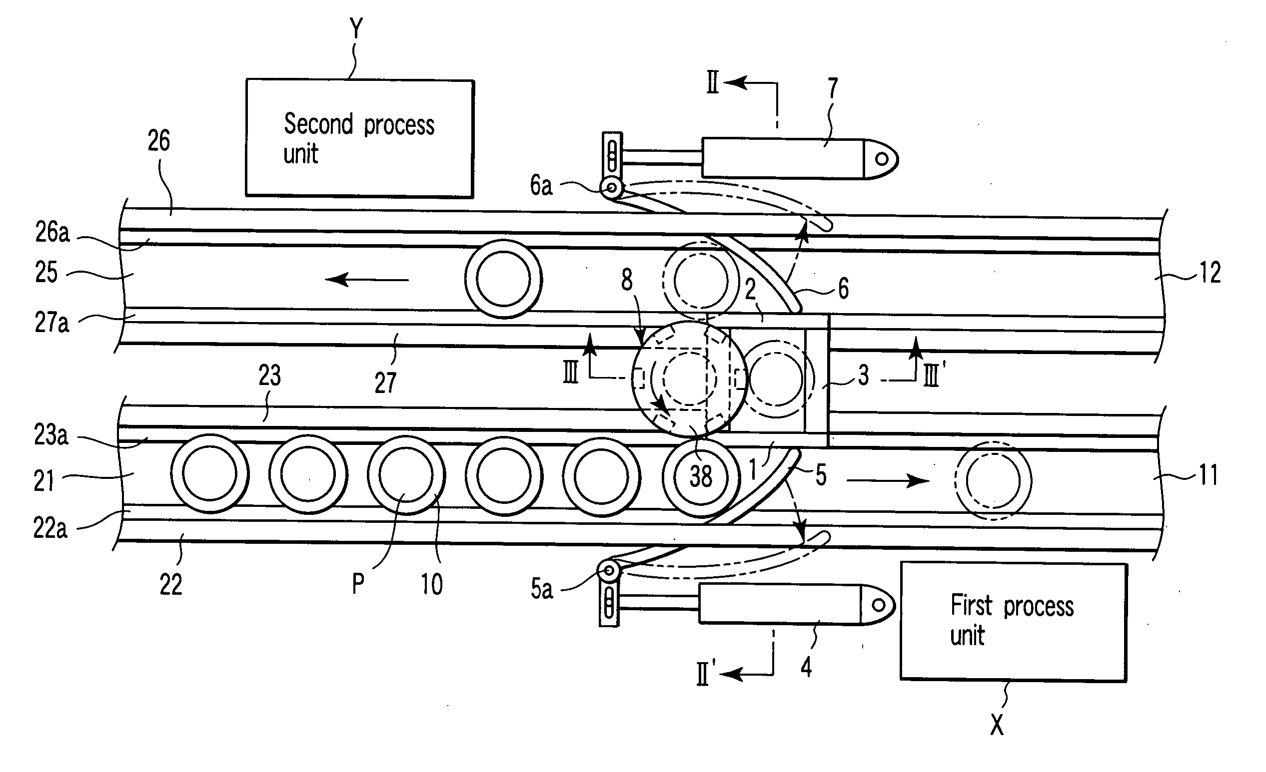
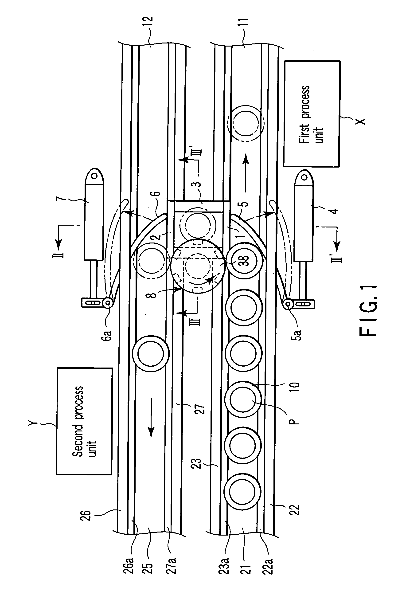
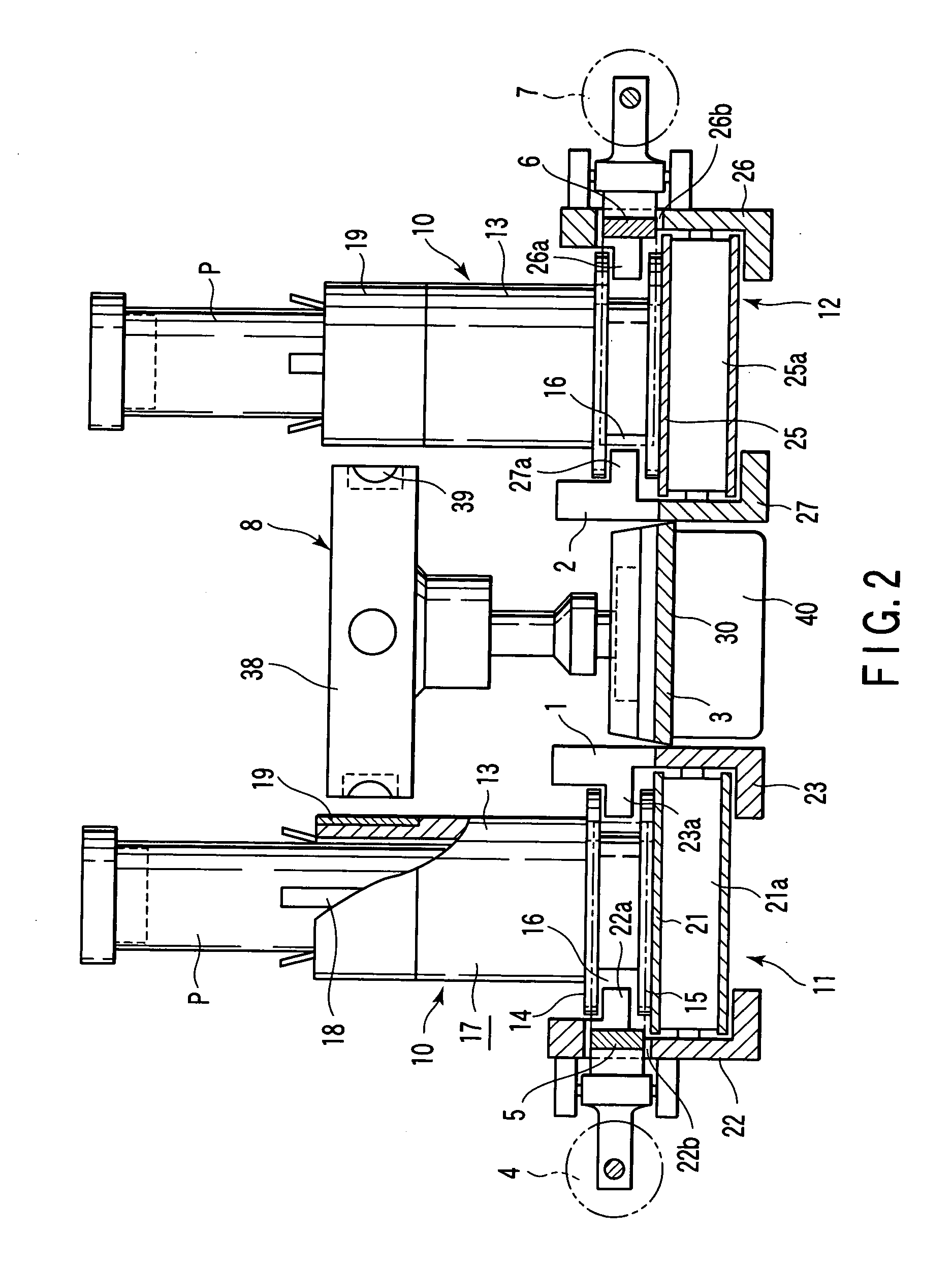
[0040]FIG. 1 is a plan view illustrating a major part of a carriage direction switching apparatus for a test-tube carriage path unit according to the invention. FIG. 2 is an enlarged sectional view taken along line II-II′ of FIG. 1. FIG. 3 is an enlarged sectional view taken along line III-III′ of FIG. 1.

[0041] Test-tube holders 10 are holders to be carried. As clearly shown in FIG. 2, each test-tube holder 10 comprises a holder main unit 17, plate springs 18 and metal ring 19.

[0042] The holder main unit 17 is formed of a synthetic resin, and has a cylindrical section 13 whose bottom is closed, and a pair of flanges 14 and 15 and an annular groove 16 therebetween, which are provided on the periphery of the lower portion of the cylindrical section 13.

[0043] The plate springs 18 are provided in the cylindrical section 13 for holding a test tube P (containing a blood sample) inserted into the holder main unit 17 through the upper opening.

[0044] The metal ring 19 is fitted on the upp...

second embodiment

[0071]FIG. 4 shows the invention.

[0072] The second embodiment differs from the first embodiment in that in the former, the second carriage path 12 is a branch carriage path perpendicular to the first carriage path 11 (alternatively, the path 12 may extend to form an acute angle to the path 11). In the second embodiment, the upstream end port of the branch carriage path with respect to the direction of carriage serves as the connecting inlet 2, and the relay member 3 is provided between this inlet and the connecting outlet 1 of the first carriage path 11.

[0073] The other structures of the second embodiment are similar to those of the first embodiment. In FIG. 4 directed to the second embodiment, elements similar to those of the first embodiment are denoted by corresponding reference numerals, and no detailed description will be given thereof.

[0074] Also in the above-mentioned structure, the direction switching mechanism 8 employs the rotary member 38 with the magnets 39 to be magne...


PUM


Abstract

There is provided a carriage direction switching apparatus for a test-tube carriage path, which comprises a first carriage path including a connecting outlet, a second carriage path including a connecting inlet, a relay member interposed between the connecting outlet and the connecting inlet, and configured to guide, to the connecting inlet, an opening/closing arm opposing the connecting outlet, and a direction switching mechanism provided adjacent to the relay member. In particular, the direction switching member includes a rotary member located at a level at which the rotary member can attract the metal ring of the test-tube holder, a plurality of magnets embedded in the outer periphery of the rotary member, and a driving motor for continuously rotating the rotary member with the magnets.

Description

CROSS-REFERENCE TO RELATED APPLICATIONS [0001] This application is based upon and claims the benefit of priority from prior Japanese Patent Application No. 2004-083109, filed Mar. 22, 2004, the entire contents of which are incorporated herein by reference. BACKGROUND OF THE INVENTION [0002] 1. Field of the Invention [0003] The present invention relates to a carriage direction switching apparatus for switching a test-tube carrier path unit that includes a first carriage path for carrying, to a first process unit, test-tube holders holding test tubes with blood samples contained therein, and a second carriage path for switching the direction of carrying the test-tube holders to a second process unit. [0004] 2. Description of the Related Art [0005] The carriage direction switching apparatus for a test-tube carrying path as shown in FIG. 5 is well known. [0006] The carriage direction switching apparatus is used to carry test-tube holders 10 that hold test tubes P containing blood sample...

Claims


Application Information

Patent Timeline
IPC IPC(8): A61J1/16B01L9/00B01L9/06B65G47/46B65G47/52B66B9/10G01N35/00G01N35/04
CPCB01L9/06G01N2035/0406G01N2035/047G01N35/04B42D1/009B42D3/12B42D15/0053B42D15/0086B42D15/0093B42D15/02G09F23/10
Inventor ITOH, TERUAKI
Owner IDS CO LTD
Why Eureka
Try Eureka