Mobile phone and vibration control method of mobile phone

a mobile phone and vibration control technology, applied in the field of mobile phone and vibration control method of mobile phone, can solve the problem that the vibration of the mobile phone may not be sufficiently transmitted to the user, and the user may then fail to notice the call/mail arrival

Inactive Publication Date: 2005-09-22
KK TOSHIBA
View PDF28 Cites 37 Cited by
  • Summary
  • Abstract
  • Description
  • Claims
  • Application Information

AI Technical Summary

Benefits of technology

[0026] Pressure applied to the mobile phone is detected at the time of call / mail arrival, and in compliance therewith vibration of the mobile phone is controlled. As a result, vibration is controlled in compliance with the degree of contact between the mobile phone and the body of the user, so that notification of an incoming call / mail by vibration can be conducted more surely.

Problems solved by technology

In this case, if the mobile phone is in the breast pocket of the user without contacting a body, vibration of the mobile phone may not adequately transmit to the user who then may fail to notice call / mail arrival.

Method used


Image

  • Mobile phone and vibration control method of mobile phone
  • Mobile phone and vibration control method of mobile phone
  • Mobile phone and vibration control method of mobile phone

Examples


first embodiment

(First Embodiment)

[0038] Hereinafter, a mobile phone according to a first embodiment of the present invention will be described with reference to the attached drawings.

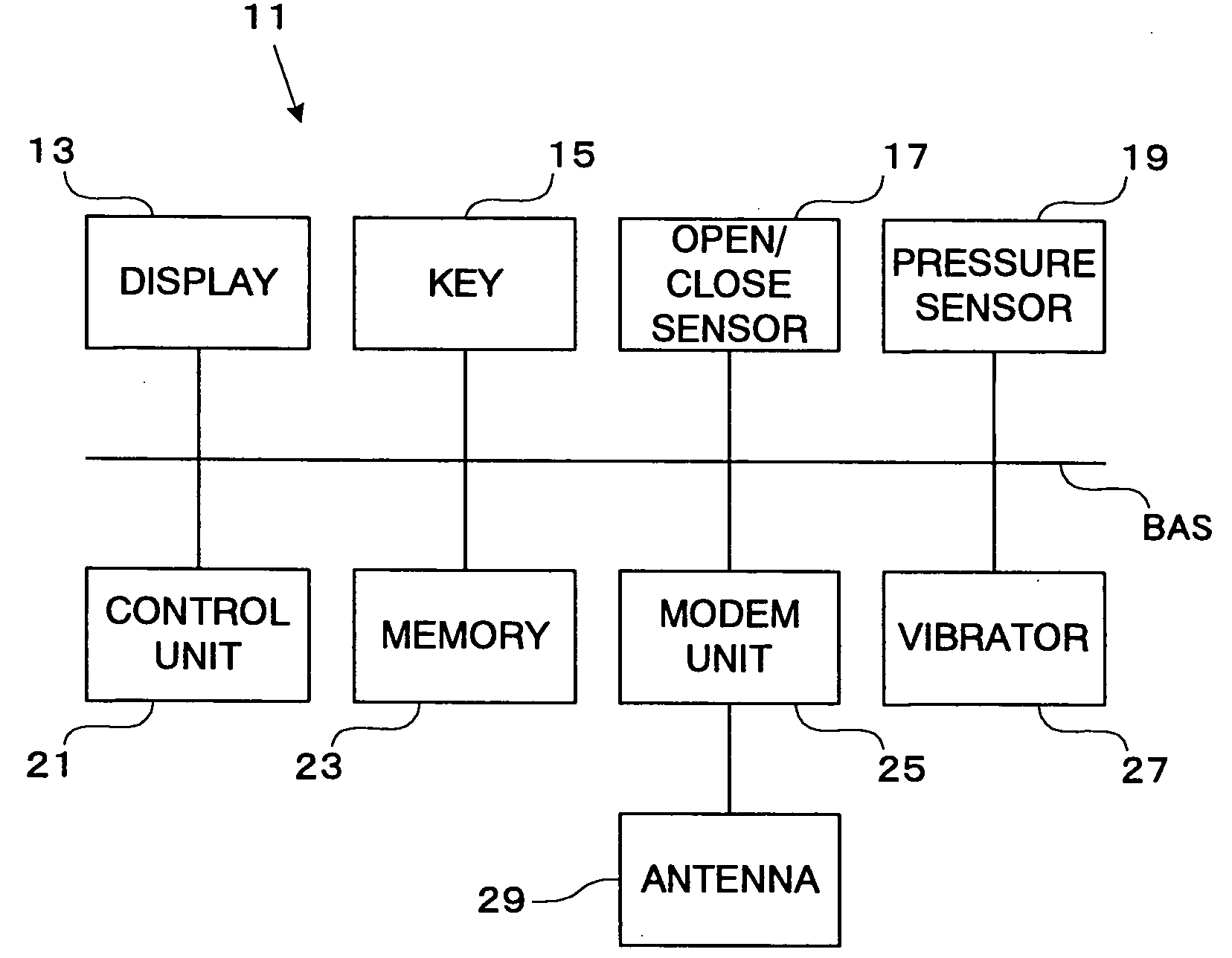
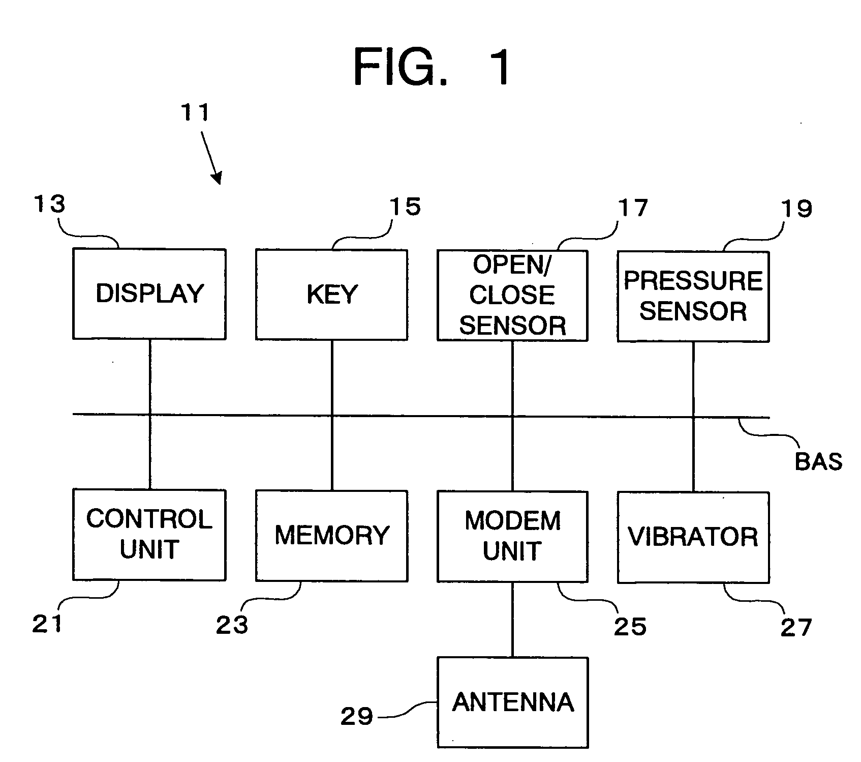
[0039]FIG. 1 is a block diagram showing a functional structure of the mobile phone 11 according to this embodiment.

[0040] As shown in FIG. 2 and FIG. 3, the mobile phone 11 is so-called foldable type, constituted with a cover (first body part) 11A and a mobile phone main body (second body part) 11B, coupled via a hinge (coupling member) 12, so as to be pivotal (openable and closable).

[0041] The mobile phone 11 has, as shown in FIG. 1, a display 13, a key 15, an open / close sensor (open / close detecting unit) 17, a pressure sensor (pressure detecting unit) 19, a control unit 21, a memory 23, a modem unit 25, and a vibrator 27.

[0042] The display 13 is, for example, a liquid crystal display, attached to an inner surface side of the cover 11A. The display 13 can display, for example, an outgoing call number, a mail addr...

second embodiment

(Second Embodiment)

[0074] Next, with reference to FIG. 9 to FIG. 11, a mobile phone according to a second embodiment of the present invention will be described. FIG. 9 is a perspective view showing an appearance of the mobile phone according to this embodiment.

[0075] Since a mobile phone 31 according to this embodiment is a non-foldable type (not foldable type) mobile phone, the open / close sensor 17 is unnecessary. The other basic structure of the mobile phone 31 is the same as those in the block diagram shown in FIG. 1, so that detailed descriptions will be restrained.

[0076] On a front surface side of the mobile phone 31, a display 13 and a key. 15 are attached. Plural keys are named generically as the key 15. On a body base plate (base plate 33) in an interior of a predetermined key 15A (such as “*” key which is positioned for example at the belowest side of the body) among the key 15, a pressure sensor 49 is mounted (see FIG. 10).

[0077] The key 15A can be structured, for examp...


PUM


Abstract

Pressure applied to a mobile phone main body is detected at the time of call/mail arrival, and in compliance therewith vibration of a vibrator of a mobile phone is controlled. As a result, vibration is controlled in compliance with a degree of contact between the mobile phone and a body of a user, so that notification of an incoming call/mail by vibration can be conducted more surely.

Description

CROSS-REFERENCE TO THE INVENTION [0001] This application is based upon and claims the benefit of priority from the prior Japanese Patent Application No. 2004-076180, filed on Mar. 17, 2004; the entire contents of which are incorporated herein by reference. BACKGROUND OF THE INVENTION [0002] 1. Field of the Invention [0003] The present invention relates to a mobile phone (for example, cellular phone) having a vibrator which vibrates at the time of call / mail arrival and a method of vibration control for a mobile phone. [0004] 2. Description of the Related Art [0005] A mobile phone can notify an incoming call / mail with vibration. More specifically, at the time of call / mail arrival the mobile phone vibrates to notify the arrival. [0006] Incidentally, in relation to a folding portable communication device, an art is disclosed in which an open / close state of two-unit type communication device main bodies which are openable / closable is detected and then switching between a vibration mode a...

Claims


Application Information

Patent Timeline
Patent Type & Authority Applications(United States)
IPC IPC(8): H04M1/02H04M1/00H04M1/725H04M19/04H04W88/02
CPCH04M19/04H04M2250/12H04M19/047
Inventor SAKAMOTO, MASASHI
Owner KK TOSHIBA
Why Eureka
Try Eureka