Channel coding/decoding apparatus and method for a CDMA mobile communication system

a mobile communication system and channel coding technology, applied in the direction of coding, code conversion, orthogonal multiplex, etc., can solve the problems of inability to correctly receive the respective service frame of the receiver, increase the error rate of the tfci bit in the same channel environment, and achieve high error correction capability

Inactive Publication Date: 2005-09-22
SAMSUNG ELECTRONICS CO LTD
View PDF9 Cites 14 Cited by
  • Summary
  • Abstract
  • Description
  • Claims
  • Application Information

AI Technical Summary

Benefits of technology

[0018] It is further another object of the present invention to provide an apparatus and method for determining optimal puncturing positions to obtain first order Reed-Muller codes having high error correcting capability.

Problems solved by technology

Therefore, if a transmission error occurs in the TFCI bits, the receiver may not correctly receive the respective service frames.
However, since the minimum distance between the coded symbols output from the encoder shown in FIG. 4 is 8, the encoder does not have the optimal codes.
If the error correction encoding scheme of FIG. 4 fails to have the optimal codes, an error rate of the TFCI bits increases in the same channel environment.
As a result, the receiver may erroneously recognize a data rate of the data frames, increasing frame error rate (FER).

Method used


Image

  • Channel coding/decoding apparatus and method for a CDMA mobile communication system
  • Channel coding/decoding apparatus and method for a CDMA mobile communication system
  • Channel coding/decoding apparatus and method for a CDMA mobile communication system

Examples


first embodiment

[0058] The first embodiment of the present invention provides an encoding apparatus and method for a transmitter based on the above-stated optimal code generation method. FIG. 6 illustrates a structure of an encoder included in a transmitter for a CDMA mobile communication system according to an embodiment of the present invention.

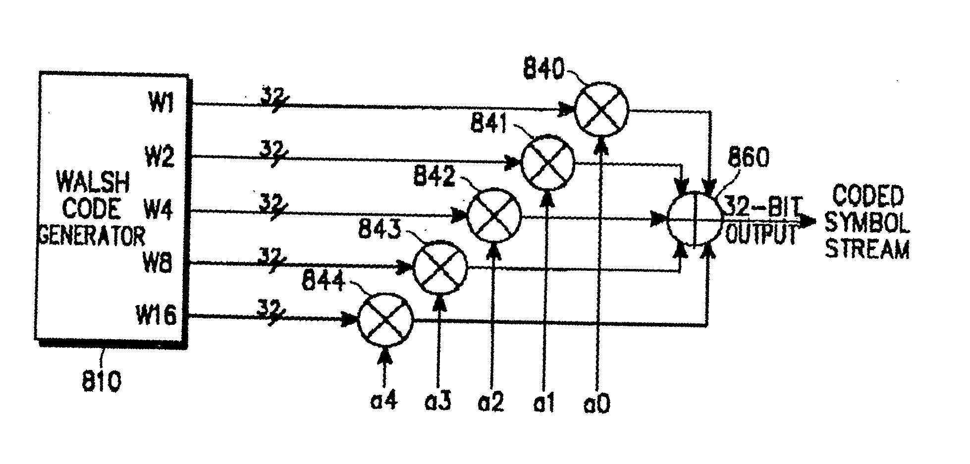
[0059] Referring to FIG. 6, a (32,5) first order Reed-Muller encoder 600 encodes 5 input information bits of a0, a1, a2, a3 and a4, and outputs a coded symbol stream comprised of 32 coded symbols.

[0060]FIG. 8 illustrates a detailed structure of the first order Reed-Muller encoder 600. Referring to FIG. 8, the 5 input information bits a0, a1, a2, a3 and a4 are provided to their associated multipliers 840, 841, 842, 843 and 844, respectively. At the same time, a Walsh code generator 810 generates Walsh codes W1, W2, W4, W8 and W16, and provides the generated Walsh codes W1, W2, W4, W8 and W16 to the associated multipliers 840, 841, 842, 843 and 844, respec...

second embodiment

[0069] Although the first embodiment has proposed a scheme for puncturing the coded symbol stream, the second embodiment proposes a scheme for puncturing the Walsh codes used for encoding before encoding the input information bits. That is, the second embodiment provides an apparatus and method for performing the puncturing and encoding operations at the same time, without the separate puncturer.

[0070]FIG. 9 illustrates a detailed structure of the encoder according to the second embodiment of the present invention. Referring to FIG. 9, five input information bits a0, a1, a2, a3 and a4 are provided to first to fifth multipliers 940, 941, 942, 943 and 944, respectively. At the same time, a Walsh code generator 910 generates 8-bit-punctured Walsh codes W1, W2, W4, W8 and W16 of length 24. The Walsh codes of length 24 output from the Walsh code generator 910 correspond to the Walsh codes of length 32 used in the first embodiment, from which 8 bits corresponding to the optimal puncturin...


PUM


Abstract

A apparatus for generating (2k-2t) first order Reed-Muller codes from 2k first order Reed-Muller codes based on k input information bits. The apparatus includes a code generator configured to generate (2k-2t) bits first order Reed-Muller codes, and an encoder for multiplying the k input information bits with the (2k-2t) bits first order Reed-Muller codes. The encoding apparatus also includes a memory for storing a number of first order Reed-Muller codes.

Description

PRIORITY [0001] This application is a Continuation of U.S. patent application Ser. No. 09 / 933,091, which was filed in the United States Patent and Trademark Office on Aug. 20, 2001, and claims priority to an application entitled “Channel Coding / Decoding Apparatus and Method for a CDMA Mobile Communication System” filed in the Korean Industrial Property Office on Aug. 18, 2000 and assigned Serial No. 2000-48726, and an application entitled “Channel Coding / Decoding Apparatus and Method for a CDMA Mobile Communication System” filed in the Korean Industrial Property Office on Aug. 21, 2000 and assigned Serial No. 2000-48732, the contents of which are hereby incorporated by reference.BACKGROUND OF THE INVENTION [0002] 1. Field of the Invention [0003] The present invention relates generally to a code generator for a CDMA mobile communication system, and in particular, to a TFCI (Transport Format Combination Indicator) code generator and a method for embodying the same. [0004] 2. Descripti...

Claims


Application Information

Patent Timeline
Patent Type & Authority Applications(United States)
IPC IPC(8): H03M13/15H03M13/00H03M13/13H03M13/21H04B1/707H04J13/12H04L1/00
CPCH03M13/136H04L1/0069H04L1/0057H03M13/6362H04J13/12
Inventor KIM, JAE-YOEL
Owner SAMSUNG ELECTRONICS CO LTD
Why Eureka
Try Eureka