
Method and apparatus for determining computer program flows autonomically using hardware assisted thread stack tracking and cataloged symbolic data

Inactive Publication Date: 2005-09-22
IBM CORP
View PDF87 Cites 105 Cited by
  • Summary
  • Abstract
  • Description
  • Claims
  • Application Information

AI Technical Summary

Benefits of technology

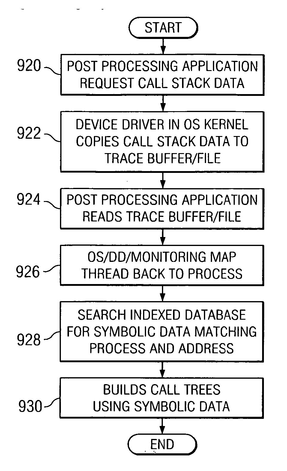
[0018] The present invention provides a method, apparatus, and computer instructions for determining computer program flows autonomically using hardware assisted thread stack tracking and cataloged symbolic data. When a new or existing thread is dispatched during execution of a computer program, the present invention provides hardware control registers that assist in allocating or identifying a thread work area where call stack entries are stored for the particular thread.

Problems solved by technology

However, software performance trace tools are often less efficient in performance and require a larger memory footprint.
A large memory footprint requires longer loading time and reduces operating efficiency of the system.
Thus, it may be difficult for a user of the trace tools to identify the modules, instructions, and such, from the pure machine code representations in the performance trace data.
As a result, the symbolic data may not be consistent with the particular version of the computer program executed during the trace.
In such a case, the supplier may continue to update the symbolic data, i.e. create new versions of the application, but fail to provide the newest version of the application to all of the clients.

Method used


Image

  • Method and apparatus for determining computer program flows autonomically using hardware assisted thread stack tracking and cataloged symbolic data
  • Method and apparatus for determining computer program flows autonomically using hardware assisted thread stack tracking and cataloged symbolic data
  • Method and apparatus for determining computer program flows autonomically using hardware assisted thread stack tracking and cataloged symbolic data

Examples


Embodiment Construction

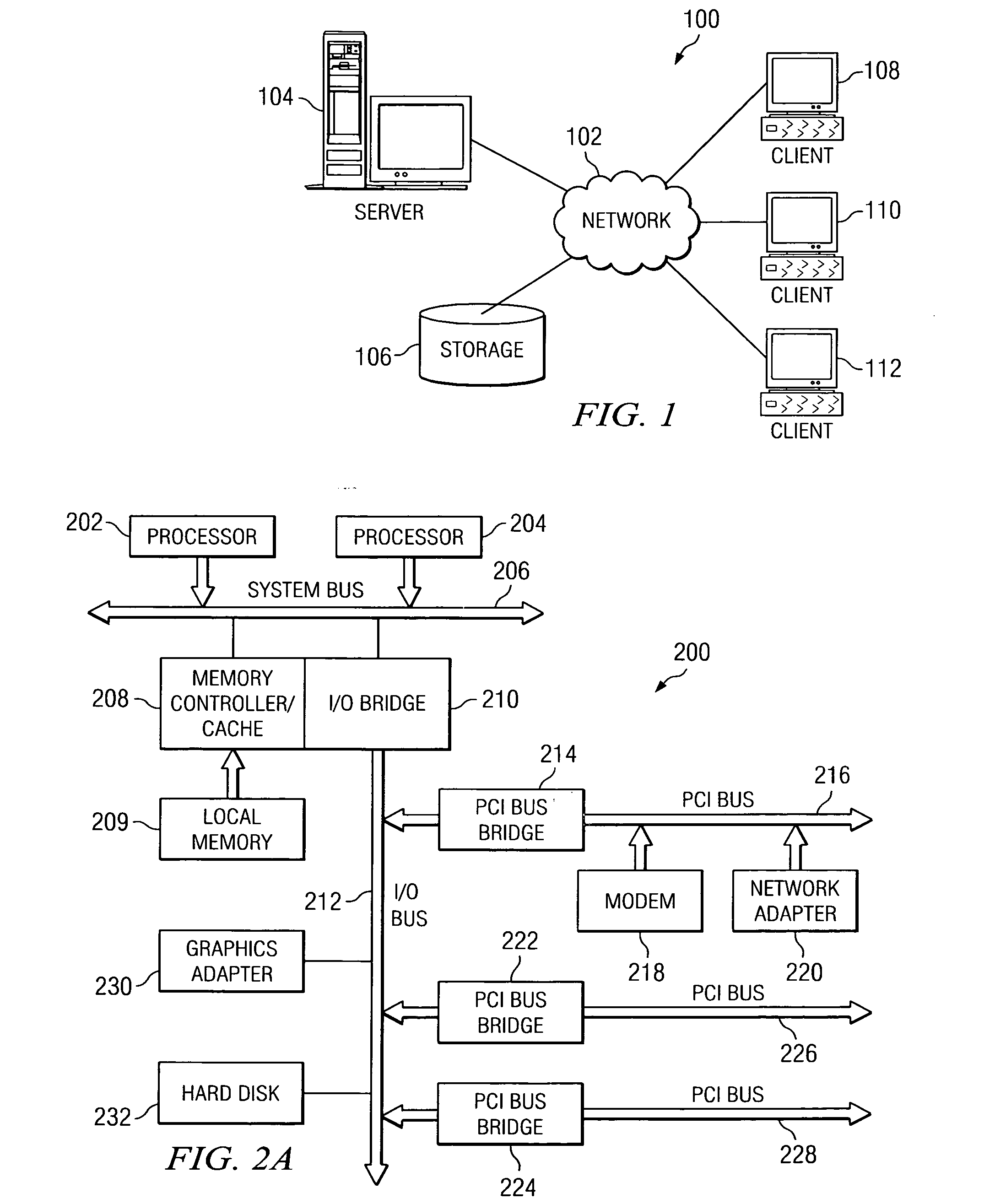
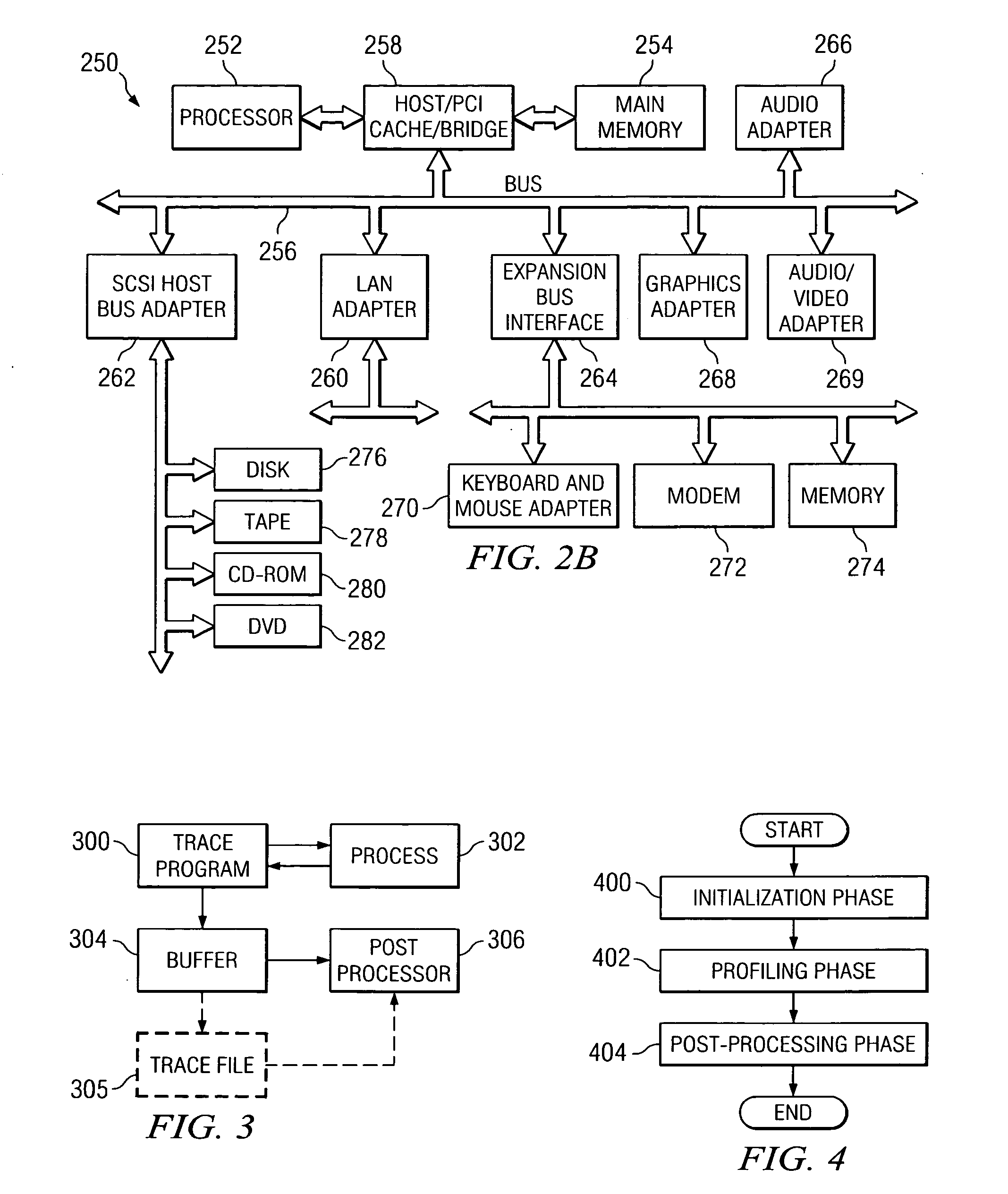
[0039] The present invention provides a method, apparatus, and computer instructions for determining computer program flows autonomically using hardware assisted thread stack tracking and cataloged symbolic data. The present invention may be implemented in a stand-alone computing device or in a network based computing device. For example, the present invention may be implemented in a personal computer, a network computer, a server, or the like. Thus, the following diagrams in FIGS. 1-2B are intended to provide a context for the operations described hereafter.

[0040] With reference now to the figures, and in particular with reference to FIG. 1, a pictorial representation of a distributed data processing system in which the present invention may be implemented is depicted. Distributed data processing system 100 is a network of computers in which the present invention may be implemented. Distributed data processing system 100 contains a network 102, which is the medium used to provide ...


PUM


Abstract

A method, apparatus, and computer instructions for determining computer flows autonomically using hardware assisted thread stack and cataloged symbolic data. When a new thread is spawned during execution of a computer program, new thread work area is allocated by the operating system in memory for storage of call stack information for the new thread. Hardware registers are set with values corresponding to the new thread work area. Upon context switch, values of the registers are saved in a context save area for future restoration. When call stack data is post-processed, the operating system or a device driver copies call stack data from the thread work areas to a consolidated buffer and each thread is mapped to a process. Symbolic data may be obtained based on the process identifier and address of the method / routine that was called / returned in the thread. Corresponding program flow is determined using retrieved symbolic data and call stack data.

Description

CROSS REFERENCE TO RELATED APPLICATIONS [0001] The present invention is related to the following applications entitled “APPARATUS AND METHOD FOR AUTONOMIC HARDWARE ASSISTED THREAD STACK TRACKING”, Ser. No. 10 / 703,658, attorney docket no. AUS920030542US1, filed on Nov. 6, 2003; “APPARATUS AND METHOD FOR CATALOGING SYMBOLIC DATA FOR USE IN PERFORMANCE ANALYSIS OF COMPUTER PROGRAMS”, Ser. No. 09 / 613,190, attorney docket no. AUS000127US1 filed on Jul. 10, 2000. Both related applications are assigned to the same assignee and are incorporated herein by reference.BACKGROUND OF THE INVENTION [0002] 1. Technical Field [0003] The present invention relates generally to an improved data processing system and, in particular, to a method and system for processing performance data in a data processing system. Still more particularly, the present invention relates to a method, apparatus, and computer instructions for determining computer program flows autonomically using hardware assisted thread st...

Claims


Application Information

Patent Timeline
IPC IPC(8): G06F9/44
CPCG06F11/3409G06F2201/88G06F2201/86G06F11/3471
Inventor DEWITT, JIMMIE EARL JR.LEVINE, FRANK ELIOTRICHARDSON, CHRISTOPHER MICHAELURQUHART, ROBERT JOHN
Owner IBM CORP
Learn More