Head joint drainage device, wall system and method for draining moisture from a head joint

a head joint and drainage device technology, applied in the direction of girders, joists, transoms, etc., can solve the problems of affecting the flow of moisture through the wall cavity, exacerbate the problem, etc., and achieve the effect of preventing the passage of moistur

Inactive Publication Date: 2005-09-29
MASONRY TECH
View PDF5 Cites 16 Cited by
  • Summary
  • Abstract
  • Description
  • Claims
  • Application Information

AI Technical Summary

Problems solved by technology

This problem is exacerbated when the exterior veneer of the wall structure is formed with modular building products, such as brick.
Such mortar can interfere with the proper flow of moisture wall through the wall cavity and, ultimately, outside of the wall cavity.

Method used


Image

  • Head joint drainage device, wall system and method for draining moisture from a head joint
  • Head joint drainage device, wall system and method for draining moisture from a head joint
  • Head joint drainage device, wall system and method for draining moisture from a head joint

Examples


Embodiment Construction

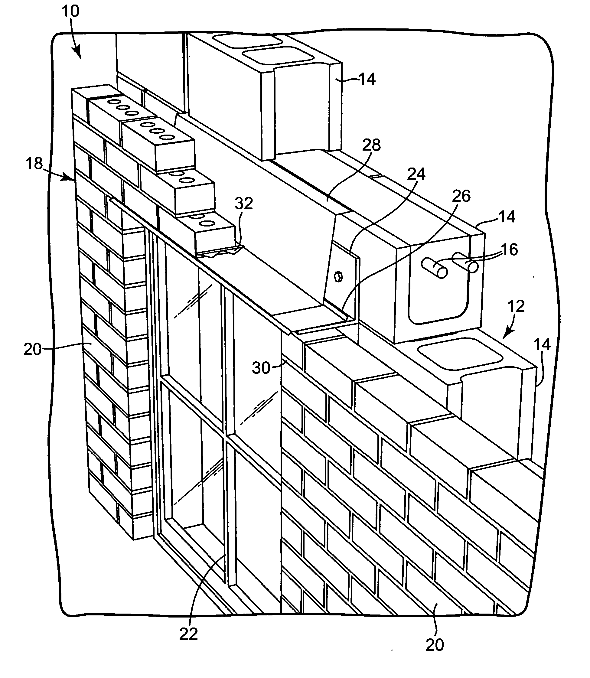
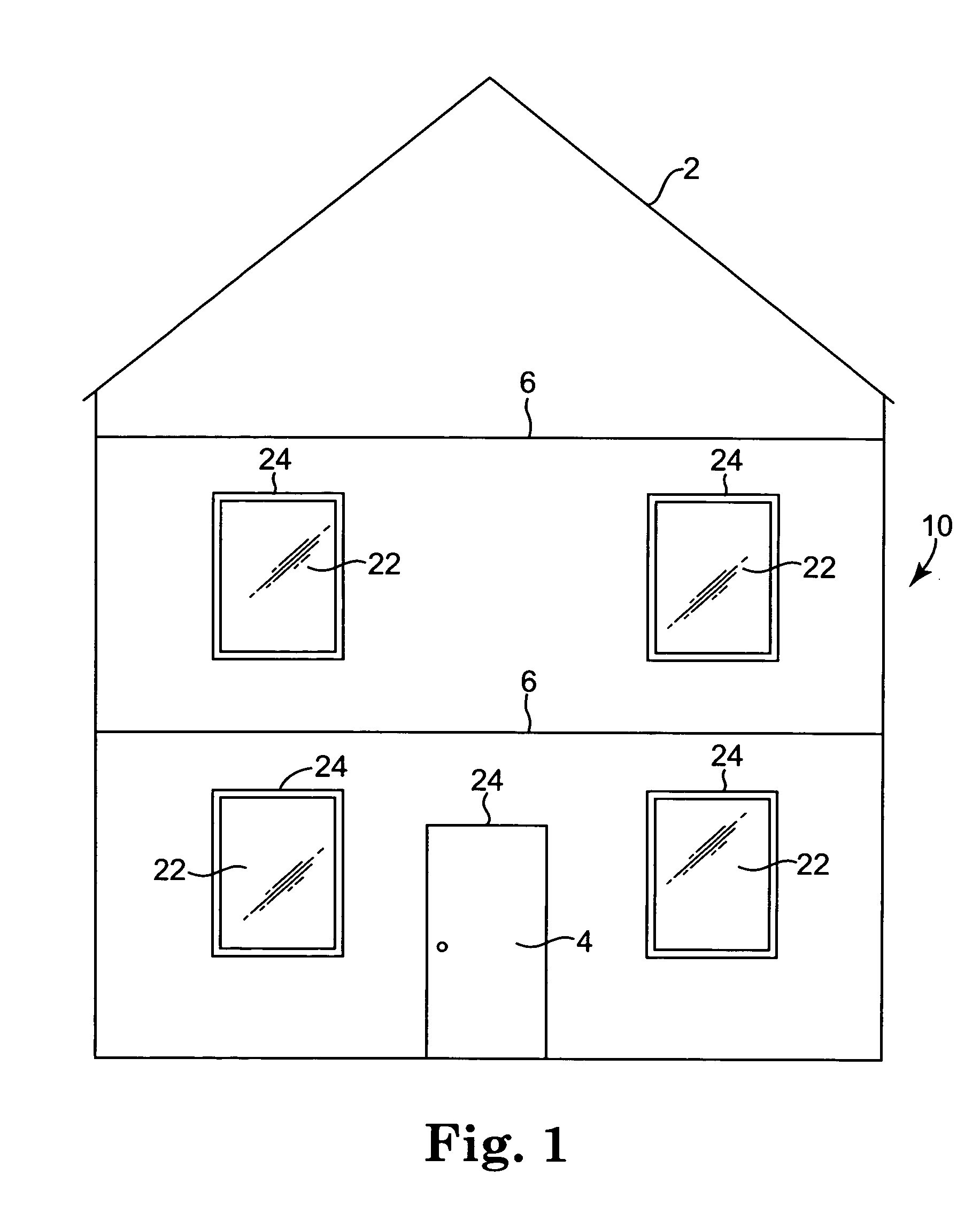
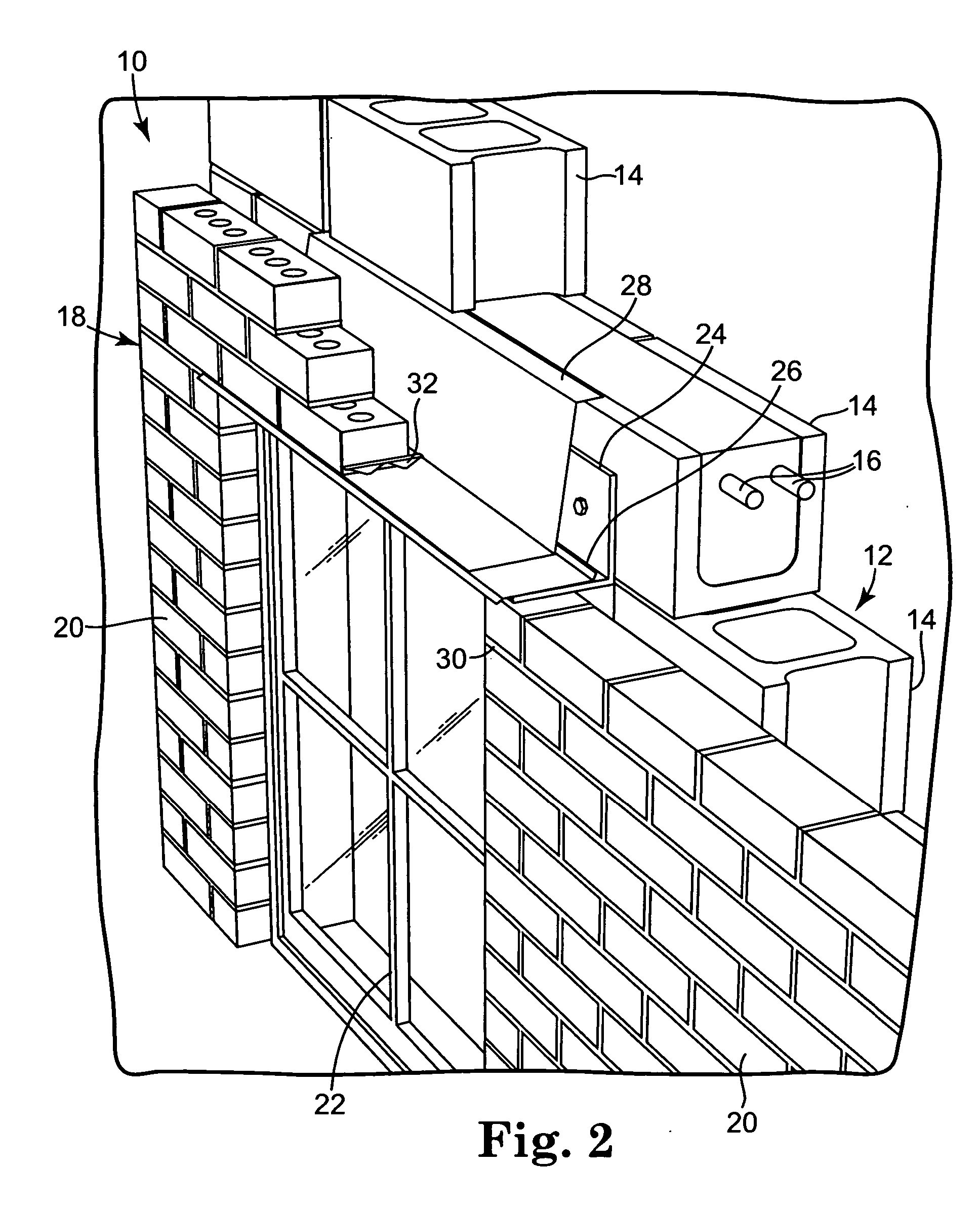
[0044] A head joint is formed in a wall structure when the wall structure has an opening in what would otherwise be an unbroken expanse of wall. Openings are commonly made in wall structures for windows and doors, for example. The wall structure essentially stops at the top of the window or door opening and, in the case of a window opening, may start again below the opening. The wall structure above the opening is typically supported by a structural header, designed to carry the load of the wall structure above the opening and spread the weight of that load the load bearing capacity of the wall structure on either side of the opening.

[0045] In the case of a wall structure having an a brick exterior, typically an exterior veneer of brick set in mortar, the weight of the wall structure above an opening is also distributed by a structural member to either side of the opening. With a brick wall structure, the load bearing member is typically called a lintel. A lintel is commonly constr...


PUM


Abstract

A wall system, head joint drainage device and method adapted to allow drainage of moisture from a head joint of a structure meeting a horizontal interruption when the wall system is formed with a plurality of building products set with mortar forming a mortar joint between adjacent ones of the plurality of modular building products. A spacer has a top portion, having a length approximately equal to a depth of the plurality of building products and a width approximately equal to a width of the mortar joint, adapted to block the mortar from reaching the horizontal interruption and has a side portion adapted to keep the portion a distance away from the horizontal interruption, the distance allowing moisture drainage from the head joint.

Description

TECHNICAL FIELD [0001] This invention relates to moisture drainage products and, more particularly, to moisture drainage products intended for incorporation in wall systems and methods for providing moisture drainage in wall systems. BACKGROUND [0002] Warm, moisture-laden air can exist in buildings including buildings in colder climates. A significant amount of moisture can be placed into the air through common household activities, such as cooking, bathing and showering. [0003] Especially in colder climates, insulation in a wall structure helps to reduce heat loss from buildings which are heated due to the cold climate. As moisture-laden air passes through the wall structure of such buildings, the moisture-laden air encounters steadily decreasing temperatures. As the air is cooled while moving from the interior of a wall structure to the exterior of the wall structure, the air can eventually reach its dew point and water vapor in the air condenses to form moisture. The result can b...

Claims


Application Information

Patent Timeline
Patent Type & Authority Applications(United States)
IPC IPC(8): E04B1/68E04B1/70E04C3/02E04F17/00E04H1/00
CPCE04F17/00E04C2003/023E04B1/7046
Inventor KOESTER, JOHN H.
Owner MASONRY TECH
Why Eureka
Try Eureka