Nano-optical color embrossing

a color embossing and nano-optical technology, applied in the field of nano-optical color embossing, can solve the problem of surface longevity very long under glass

Inactive Publication Date: 2005-09-29
FAHRENBACH JUERGEN +1
View PDF2 Cites 37 Cited by
  • Summary
  • Abstract
  • Description
  • Claims
  • Application Information

AI Technical Summary

Problems solved by technology

Such surfaces last very long under glass, but not when carried in a wallet on a daily basis.

Method used


Image

  • Nano-optical color embrossing
  • Nano-optical color embrossing
  • Nano-optical color embrossing

Examples


Embodiment Construction

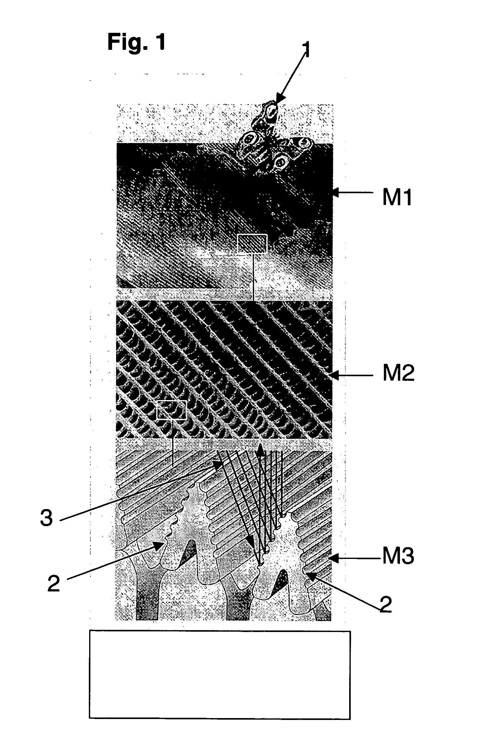
[0021]FIG. 1 is a schematic illustration of a section of a wing of a butterfly 1 in three different magnifications M1, M2, M3 in a scanning electron microscope. The magnification increases from top to bottom so that the wing's rip structure 2 is visible at the highest magnification M3 at the bottom of FIG. 1. This rip structure 2 functions as a step grating and generates the iridescent interference colors visible on the butterfly's wings. Light incident on the wing's rip structure 2 is indicated through arrows 3.

[0022] Visible light is in the wavelength range between about 400 nm (violet) and about 690 nm (red), with blue at about 486 nm, green at about 527 nm and yellow at about 589 nm. These wavelengths determine the geometric dimensions of the intended structure that generates a structure color, as exemplary shown in FIG. 1. In the bottom part of FIG. 1, at the magnification M3, an observer's eye registers that part of light, which is reflected on the rip structure 2, as a color...


PUM


Abstract

An apparatus for embossing a surface with a nano-optical color structure includes a monolithic material. The monolithic material is mounted to a carrier and has an active area facing away from the carrier and, in use, towards a surface to be embossed. The active area has a surface structure with at least one predetermined nano structure that causes in the surface to be embossed a structure that generates a predetermined color structure when exposed to visible light.

Description

CROSS REFERENCE TO RELATED APPLICATIONS [0001] The present application is a continuation application of international application no. PCT / DE2003 / 003806, filed on Nov. 16, 2003, which designated the United States and was pending at the time of designation and the filing of the present application; and further claims priority to German patent application Ser. No. 10 / 253,648.1, filed Nov. 16, 2002; both of which are herewith incorporated by reference.BACKGROUND OF THE INVENTION [0002] The invention relates to a method and an apparatus for manufacturing surface structures using interferences at certain wavelengths that produce pure colors, or through creation of so-called structure colors. [0003] Color surface structures are known, for example, through the Australian One Ounce Silver Dollar. As shown in FIG. 7, the surface of the Australian silver dollar includes a color kangaroo. Color surfaces, such as those of the Australian silver dollar, are produced through applying layers of pain...

Claims


Application Information

Patent Timeline
Patent Type & Authority Applications(United States)
IPC IPC(8): B44B5/02B44C1/24
CPCB44B5/026G03H2270/13G03H1/028
Inventor FAHRENBACH, JUERGENFELLENBERG, STEFAN
Owner FAHRENBACH JUERGEN
Why Eureka
Try Eureka