

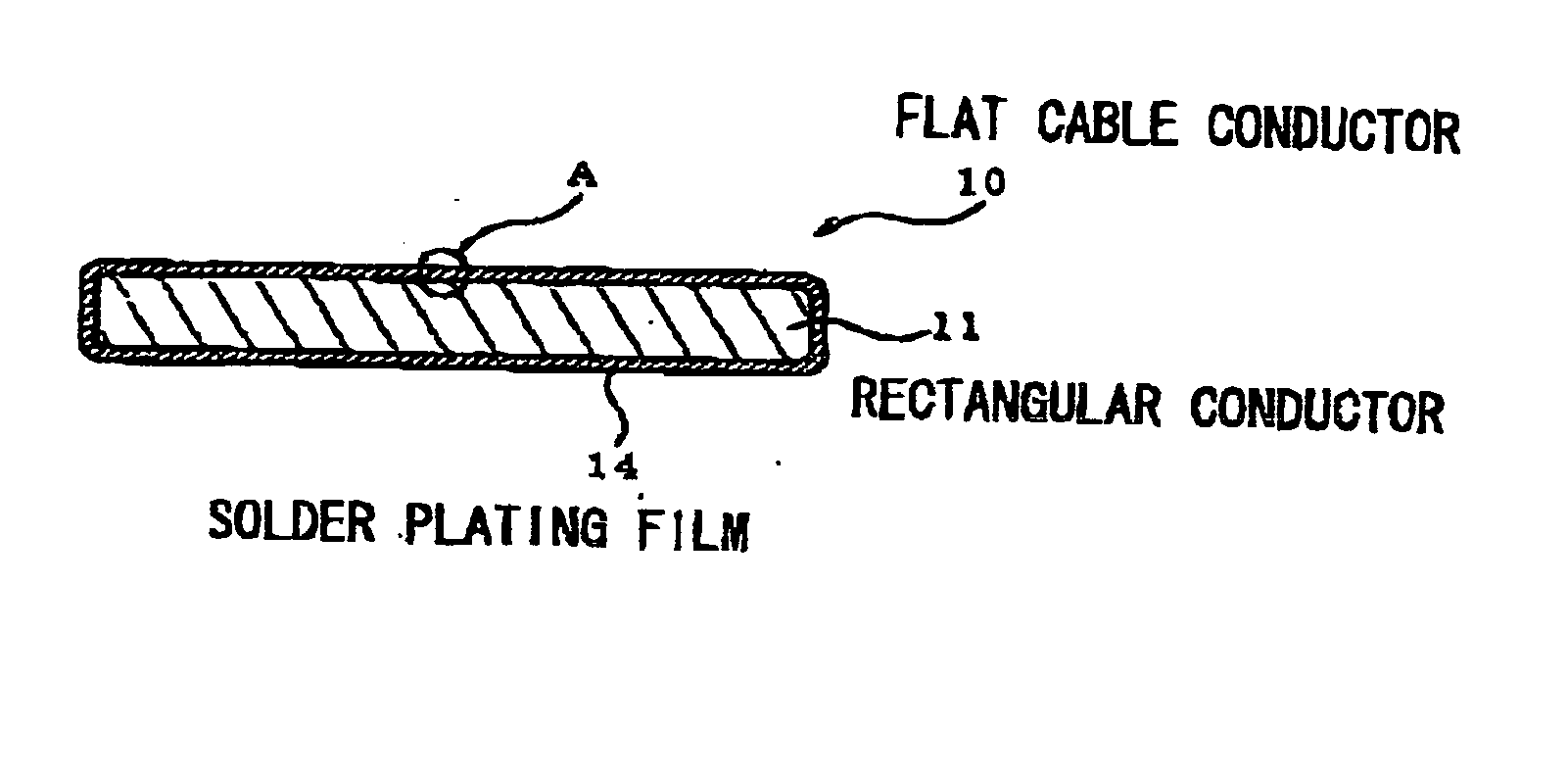
Flat cable conductor, method of making the same and flat cable using the same
a technology of flat cable and conductor, which is applied in the direction of flat/ribbon cables, insulated cables, cables, etc., can solve the problems of inferior pb-free solder plating and unsatisfactory whisker generation, and achieve the effect of increasing manufacturing costs
- Summary
- Abstract
- Description
- Claims
- Application Information
AI Technical Summary
Benefits of technology
Problems solved by technology
Method used
Image

Examples
example 1
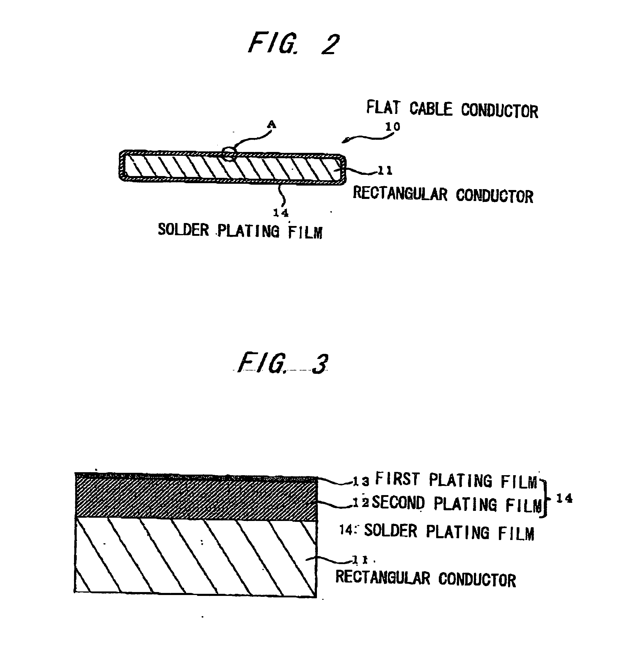
[0083] A 6 μm thick Sn plating film is formed around a copper wire of Φ6 mm by electroplating, and then a 1 μm thick pure Ag plating film is formed thereon by flash plating. Then, the Ag plating copper wire is cold-drawn to Φ0.1 mm and is processed by a rolling mill roll into a precise rectangular wire with a thickness of 0.05 mm and a width of 0.32 mm.
[0084] The precise rectangular wire is subjected to the diffusion process using an electric annealer so as to have a flat cable conductor. In this process, the power supplying conditions are controlled to be a voltage of 10 V, a current of 5.8 A and a line speed of 100 m / min such that the Ag concentration at the surface of solder plating film is 28 wt % after the diffusion process SIMS (secondary ion mass spectrometry) is used for the quantitative analysis of the Ag concentration at the surface of solder plating film.
[0085] The twenty annealed flat cable conductors are in parallel arranged into a conductor array at pitches of 0.5 mm...
example 2
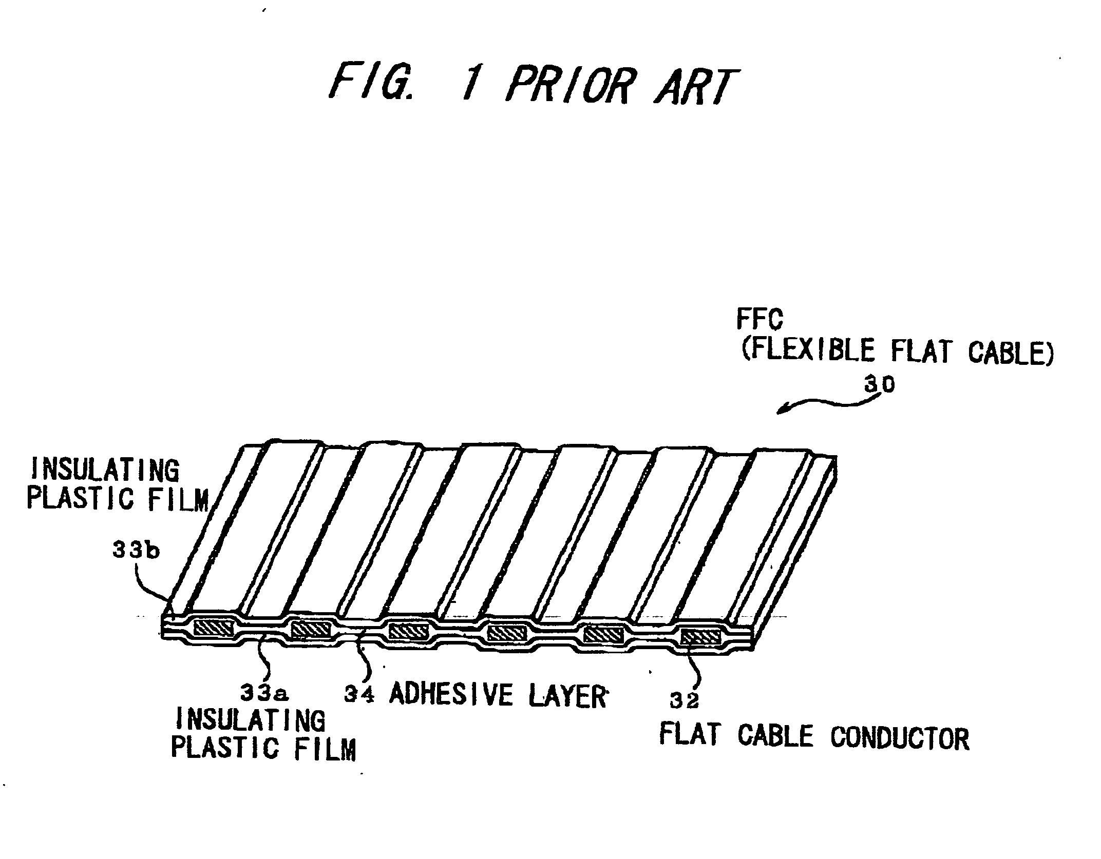
[0086] In Example 2, a FFC structured as shown in FIG. 1 is produced by the same process as Example 1 except that a 1 μm pure Zn plating film is formed by flash plating on the Sn plating copper wire. The flat cable conductor of the FFC has the solder plating film that is composed of a Sn—Cu alloy gradient plating film on the inner circumference and a Sn—Zn alloy gradient plating film on the outer circumference.
PUM
| Property | Measurement | Unit |
|---|---|---|
| Thickness | aaaaa | aaaaa |
| Concentration | aaaaa | aaaaa |
Abstract
Description
Claims
Application Information