Method for applying a shim

Inactive Publication Date: 2005-09-29
FENWICK ALLAN
View PDF9 Cites 15 Cited by
  • Summary
  • Abstract
  • Description
  • Claims
  • Application Information

AI Technical Summary

Benefits of technology

[0011] In accordance with an aspect of the present invention, there is provided a method for attaching a shim to a predefined component in a braking system comprising the steps of: applying a liquid shim to the predefined component, the liquid shi comprising A granulated liquid capable of adhering to the predefined component and being resistant to rust; and drying the liquid shim to form a shim attached to the predefined component, the shim capable of dampening vibration

Problems solved by technology

Any vibration or movement of the pads within the caliper can cause noise which is associated with the braking.
There are many causes of noise other than the brake pads.
However, any noise which can be detected is almost always blamed on the brake pad.
However, application of the shims increases the cost of the manufacturing process.
Further, the process of attaching die shim by gluing, riveting or snapping-on is time consuming and, accordingly, may slow the brake pad production process.
Yet further, depending on how the shim is attached, it may become loose and either fall off the brake pad or create more noise due to vibration.

Method used


Image

  • Method for applying a shim
  • Method for applying a shim

Examples


Embodiment Construction

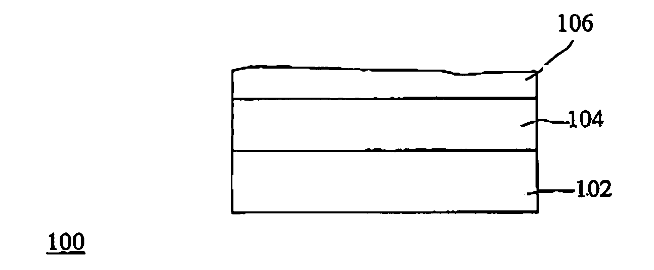
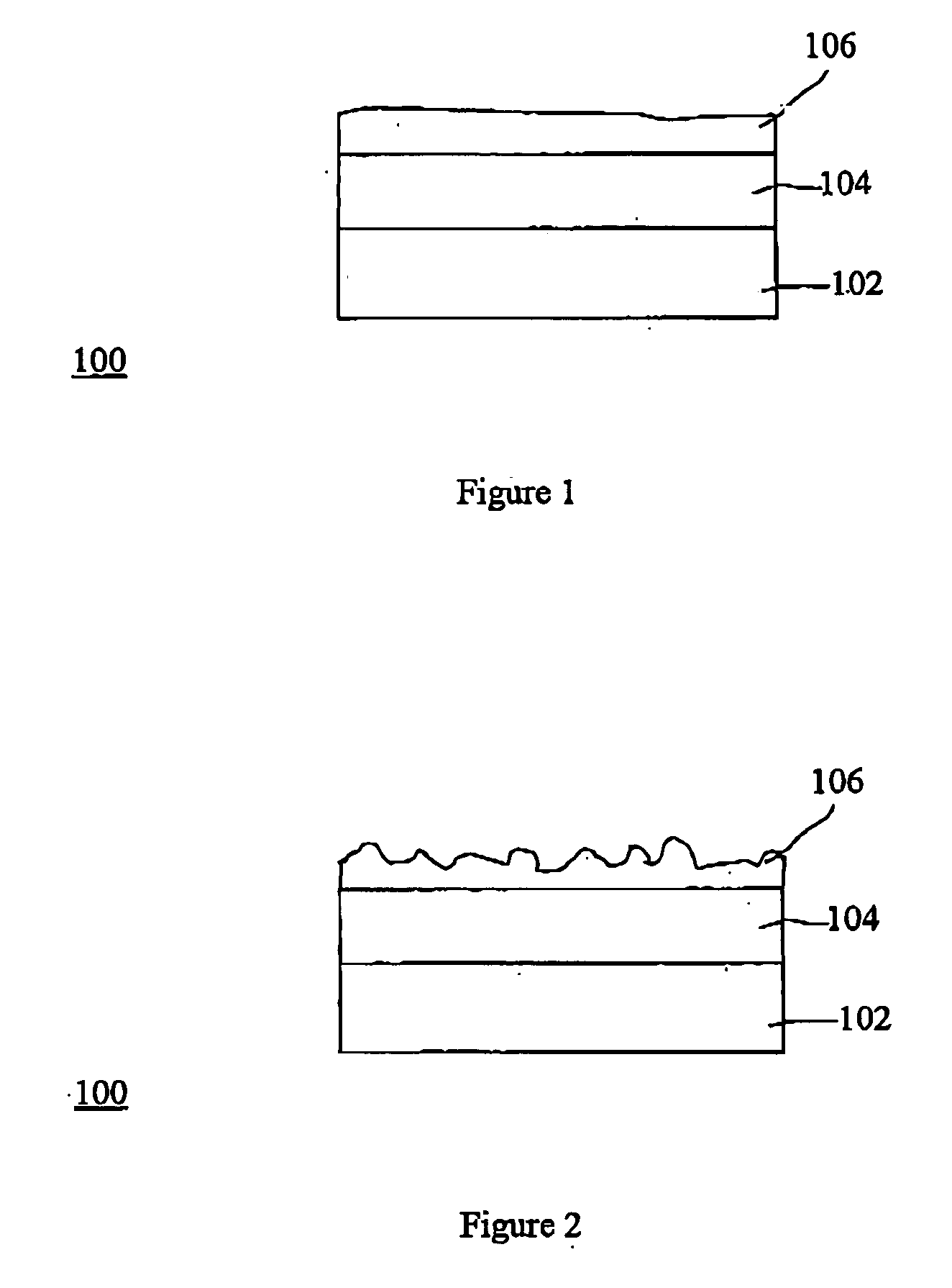
[0015] For convenience, like numerals in the description refer to like structures in the drawings. Referring to both FIGS. 1 and 2 a brake pad is illustrated generally by numeral 100. The brake pad 100 includes a friction material 102, a backing plate 104 and a shim 106. In accordance with an embodiment of the present invention, the shim 106 is formed by the application of a liquid shim to the brake pad, which has then dried. The liquid shim can be applied to the brake pad by spraying, direct application or other method that may be known in the art.

[0016] Typically, if the liquid shim is applied to the brake pad by spraying, the liquid is delivered through a nozzle attached to a spray gun. Air or electric force is used to deliver the spray If the liquid shim is applied to the brake pad by direct application, the liquid shim may be brushed on or rolled on. Rolling is often preferred to brushing for mass application as it simpler to implement on a production line. For example, the br...


PUM

PropertyMeasurementUnit
Electrical resistanceaaaaaaaaaa
Frictionaaaaaaaaaa

Abstract

A method is provided for attaching a shim to a predefined component in a breaking system. The method comprises the following steps. A liquid shim is applied to the predefined component, the liquid shim comprising a granulated liquid capable of adhering to the predefined component and being resistant to rust. The liquid shim is dried to form a shim attached to the predefined component, the shim capable of dampening vibration.

Description

[0001] The present invention relates generally to disc brakes and, specifically to disc brakes have shims attached thereto, and claims priority from Canadian Application No. 2,462,355. BACKGROUND OF THE INVENTION [0002] A disc brake pad comprises two main components. The first component is a friction material for contacting a rotor in order to provide braking action for slowing or stopping a vehicle. The second component is a backing plate that supports the friction material. The friction material is attached to the backing plate. [0003] Typically, the friction material is manufactured by processing powders, mixing them and pressing them into various shapes. The shape of the friction material corresponds with shape of the backing plate for facilitating an easy fit when installing the brake in the vehicle. Typically, the backing plates are made of commercial grade metal and get their shape and dimensions from being either mechanically stamped out on a press or being blanked out on a ...

Claims


Application Information

Patent Timeline
IPC IPC(8): C23F11/12F16D65/00F16D65/097F16D69/00F16F15/02
CPCF16D65/0025
Inventor FENWICK, ALLAN
Owner FENWICK ALLAN
Why Eureka
Try Eureka