
Image heating apparatus of electromagnetic induction heating type

a heating apparatus and electromagnetic induction technology, applied in the field of image heating apparatus, can solve the problems of difficult removal of coil from jig, inability to insert coil b>2/b> into the fixing roller, and coil damage, etc., and achieve the effect of convenient assembly

Active Publication Date: 2005-09-29
CANON KK
View PDF14 Cites 0 Cited by
  • Summary
  • Abstract
  • Description
  • Claims
  • Application Information

AI Technical Summary

Benefits of technology

The present invention aims to provide an image heating apparatus that is easy to assemble and can suppress nonuniform heating. The apparatus includes a heating member and two coil units that generate magnetic fields to induce an eddy current in the heating member. The technical effects of the invention include improved heating efficiency, reduced energy consumption, and improved image quality.

Problems solved by technology

However, it is difficult to remove the coil from the jig if the coil actually covers the 300° area.
On the other hand, inserting the coil 2 into the fixing roller is not so easy since the strands of the coil are usually composed of copper wires, which lack rigidity.
Although insertion of the coil into the fixing roller could be facilitated by attaching the coil to a holder, there is still a problem and the coil could be damaged if the coil bumps against the fixing roller.
Furthermore, it is difficult to set the nonrigid coil in place while ensuring a desired distance between the coil and the fixing roller along the length of the fixing roller.
When the coil and the fixing roller are not spaced apart from each other as designed, temperature distribution on the fixing roller becomes uneven causing a failure in fixing toner in an electrophotographic process and uneven sheet surface treatment in an ink-jet process.
In addition, the coil 2 obtained by joining two halves at the junction portion 21 is poor in mass-producibility and is difficult to handle.

Method used


Image

  • Image heating apparatus of electromagnetic induction heating type
  • Image heating apparatus of electromagnetic induction heating type
  • Image heating apparatus of electromagnetic induction heating type

Examples


first embodiment

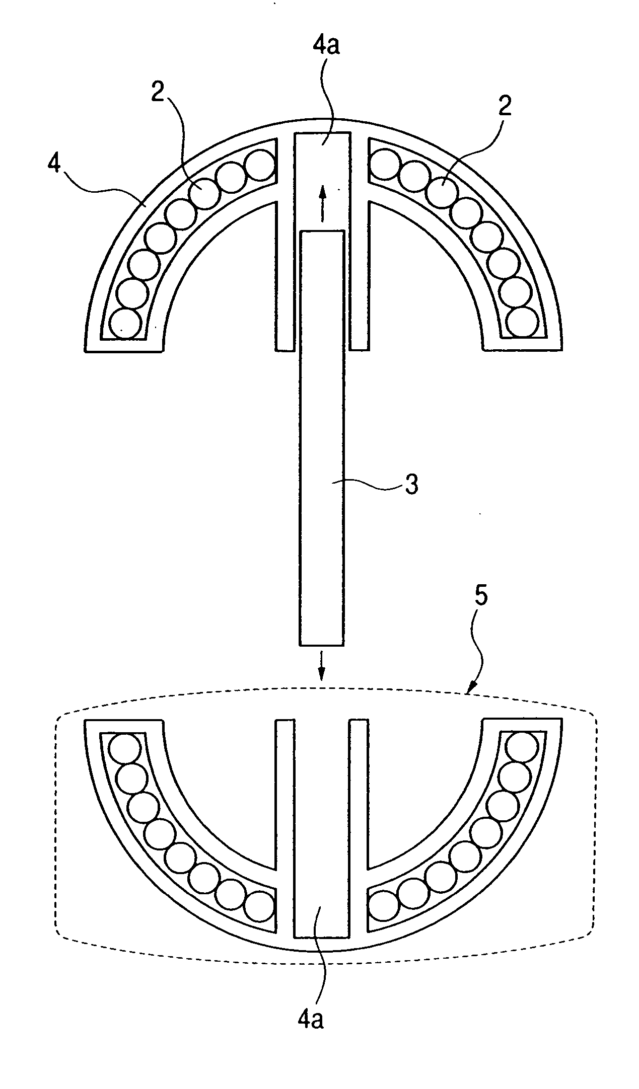
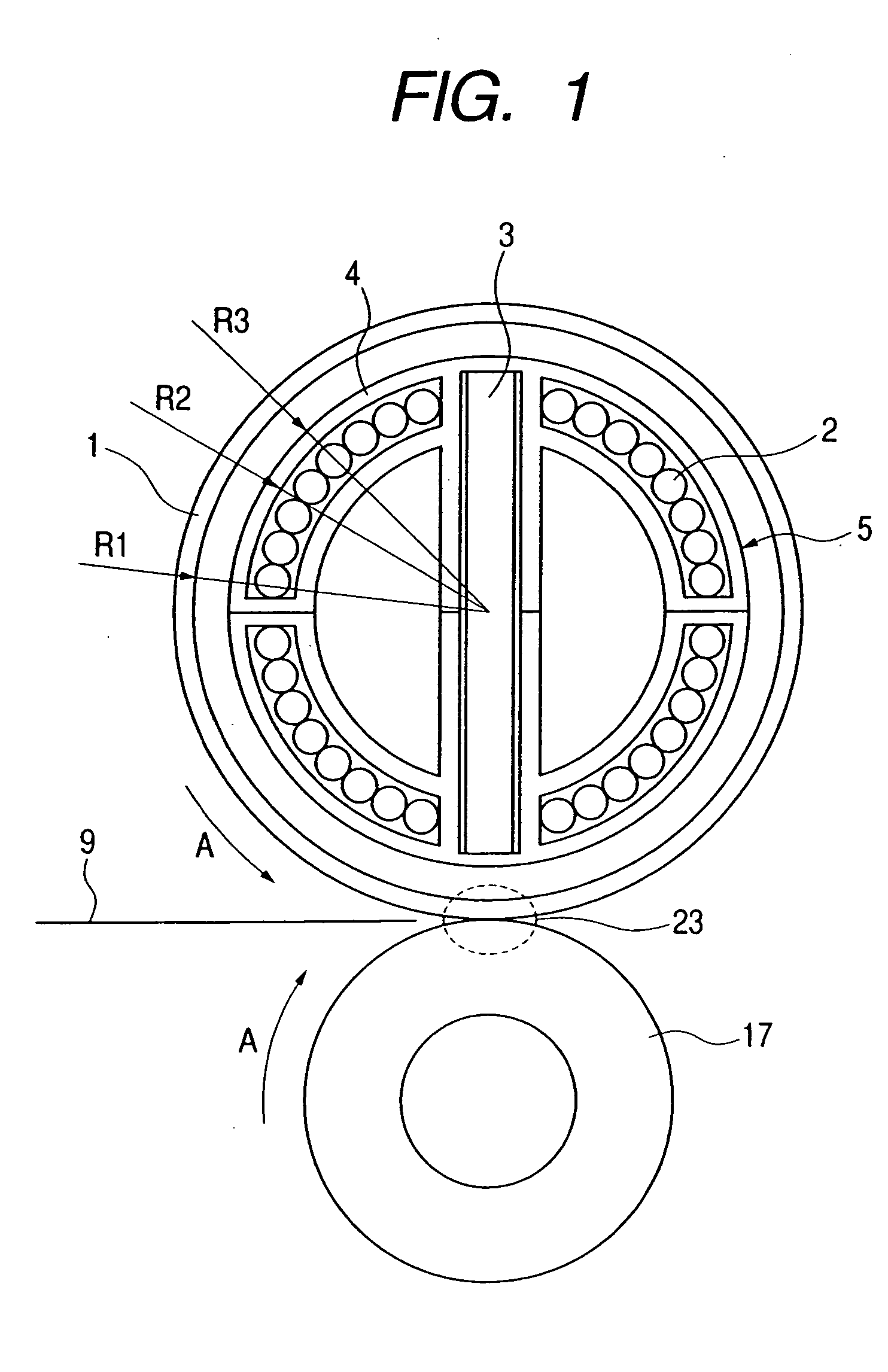
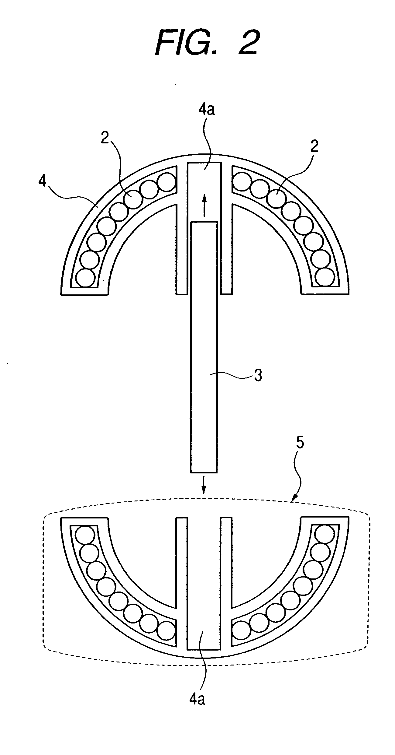
[0033] A description is given with reference to FIGS. 1 and 2 on a heating apparatus and its two coil units according to this embodiment. In FIG. 1, a heating roller 1 is a cylindrical electroconductive member (heating member) and is supported in a manner that allows the heating roller 1 to rotate about the central axis of the cylinder. The electroconductive member constituting the heating roller 1 is an iron, nickel, stainless steel, or other member that has magnetic characteristics.

[0034] Inside the heating roller 1, two semi-cylindrical coil units (a first coil unit and a second coil unit) 5 are joined together to form an approximately cylindrical (or columnar) shape since the cross-section of each of the first coil unit and the second coil unit is arced, and the resultant cylinder is centered on the rotation axis of the heating roller 1. The combined coil units are fixed to a side plate (not shown) of the heating apparatus and thus prevented from rotating. The resultant coil is...

second embodiment

[0063]FIG. 4 is a schematic sectional view of a heating apparatus according to a second embodiment.

[0064] In this embodiment, two coil core units (coil units) 6 are joined to each other, and each coil core unit is composed of a coil 2 for generating a magnetic field, a core 3 composed of a magnetic body, and a holder 4 made of phenol resin. The coil 2, the core 3, and the holder 4 are unitarily formed. For the rest, the heating apparatus of this embodiment and the heating apparatus of the first embodiment are structured similarly.

[0065] That is, the core 3 is added to the coil 2 and the holder 4 in integral molding to constitute the coil core unit 6 in this embodiment. This embodiment is thus improved in ease of assembling work as well as in work efficiency since the step of inserting the core 3 is eliminated.

[0066] This embodiment also has an effect of reducing problems brought around by the core rattling, such as chipping and a change in characteristic. The coil core units 6 ar...

third embodiment

[0069]FIG. 5 is a schematic sectional view of two coil units 5 of a third embodiment taken along a line B-B, a side view of the two coil units, and a plan view of one of the coil units.

[0070] In the third embodiment shown in FIG. 5, each coil unit 5 has an approximately semi-cylindrical shape and includes a holder 4. The coil units 5 are joined to each other at surfaces 4b of each holder 4. Two convex holding portions 7 are arranged diagonally from each other and two concave holding portions 8 are arranged diagonally from each other in the vicinity of four corners of the surface 4b. The convex holding portions and the concave holding portions are referred to as junction portions.

[0071] Each convex holding portion 7 is an approximately rectangular column that protrudes vertically from the associated surface 4b. A claw 7a is provided in each side face in the coil unit cylinder axis direction of the rectangular column. Each convex holding portion 7 is inserted into the associated con...


PUM


Abstract

The image heating apparatus includes a heating member, a first coil unit having a first holder in which a first excitation coil is sealed, the first excitation,coil being provided for generating a magnetic field to induce an eddy current in the heating member, and a second coil unit having a second holder in which a second excitation coil is sealed, the second excitation coil being provided for generating a magnetic field to induce an eddy current in the heating member. The image heating apparatus having such structure enables easy assembly work while being capable of conducting nonuniform heating

Description

BACKGROUND OF THE INVENTION [0001] 1. Field of the Invention [0002] The present invention relates to an image heating apparatus suitable as a heat-fixing apparatus mounted in an image forming apparatus such as a copying machine or a printer and, more particularly, to an image heating apparatus of electromagnetic induction heating type. [0003] 2. Related Background Art [0004] A heating apparatus of electromagnetic induction heating type produces heat from an eddy current that is generated by placing an electroconductive member (e.g., an electromagnetic induction heat generating member, an inductive magnetic material, or an electroconductive material absorptive of magnetic fields) in a magnetic field. For example, this type of heating apparatus is effective, in an electrophotographic, electrostatic recording, magnetic recording, or other image forming apparatus, as a heat-fixing apparatus for heating a recording medium that carries an unfixed toner image and thus obtaining a permanent...

Claims


Application Information

Patent Timeline
Patent Type & Authority Applications(United States)
IPC IPC(8): G03G15/20H05B6/14H05B6/36H05B6/44
CPCH05B6/145G03G15/2053
Inventor SUZUKI, HITOSHI
Owner CANON KK
Learn More