Electro-luminescence display device and driving method thereof

Active Publication Date: 2005-09-29
LG DISPLAY CO LTD
View PDF6 Cites 17 Cited by
  • Summary
  • Abstract
  • Description
  • Claims
  • Application Information

AI Technical Summary

Benefits of technology

[0021] An object of the present invention is to provide an electro-luminescence display device and a driving method thereof wherein a rise in

Problems solved by technology

However, the threshold voltage value “Vth” of the driving thin film transistor T2 deteriorates with the lapse of time.
In addition, as the threshold voltage Vth of the driving thin film transistor T2 increases, a current amount flowing through th

Method used


Image

  • Electro-luminescence display device and driving method thereof
  • Electro-luminescence display device and driving method thereof
  • Electro-luminescence display device and driving method thereof

Examples


Embodiment Construction

[0038] Reference will now be made in detail to the preferred embodiments, examples of which are illustrated in the accompanying drawings.

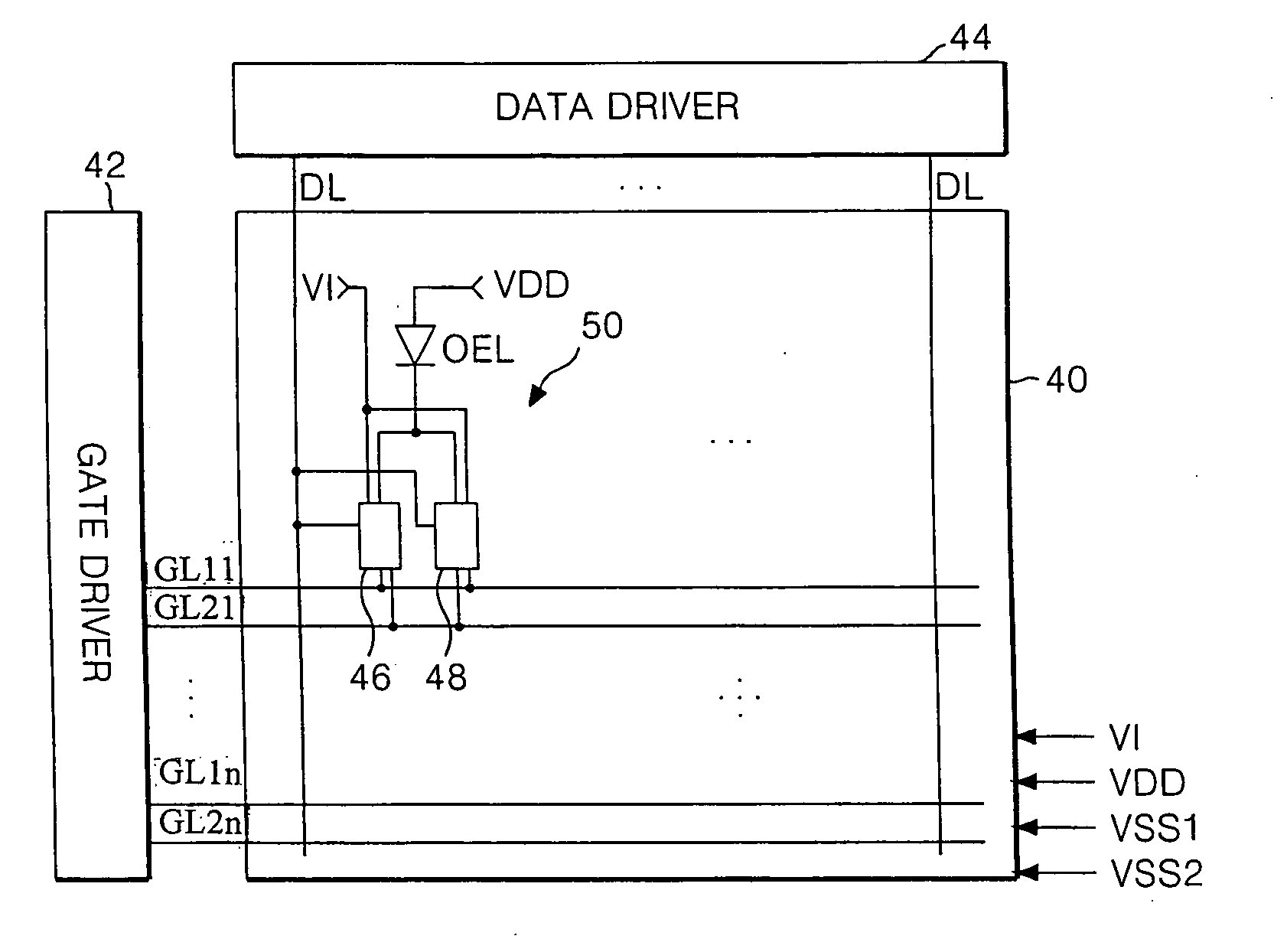
[0039]FIG. 5 is a schematic block diagram illustrating an electro-luminescence display device according to an embodiment of the present invention. In FIG. 5, an electro-luminescence (EL) display device includes an EL panel 40 having a plurality of first gate lines GL11 . . . GL1n, a plurality of second gate lines GL21 . . . GL2n, and a plurality of data lines DL, the gate lines GL1 . . . GL In and GL21 . . . GL2n intersecting the data lines DL. The number of the first gate lines GL11 . . . GL1n may be the same as the number of the second gate lines GL21 . . . GL2n, such that each of the second gate lines GL21 . . . GL2n is paired with a respective one of the first gate lines GL11 . . . GL1n for a horizontal display line of the EL panel 40.

[0040] In addition, the EL display device includes a gate driver 42 for driving the first and second gate lin...


PUM


Abstract

An electro-luminescence display device includes an electro-luminescence panel having a plurality of pixels at pixel areas defined by intersections between data lines and first and second gate lines, each of the pixels including: an electro-luminescence cell connected to receive a supply voltage, and a first cell driver and a second cell driver for alternately controlling a current flow into the electro-luminescence cell.

Description

[0001] The present application claims the benefit of Korean Patent Application No. P2004-20349 filed in Korea on Mar. 25, 2004, which is hereby incorporated by reference. BACKGROUND OF THE INVENTION [0002] 1. Field of the Invention [0003] The present invention relates to an electro-luminescence display (ELD) device, and more particularly, to an electro-luminescence display device and a driving method thereof that prevents a rise in a threshold voltage of a driving thin film transistor at each pixel and provides stable display brightness. [0004] 2. Discussion of the Related Art [0005] Many efforts have been made to research and develop various flat display devices, such as liquid crystal display (LCD) devices, field emission display (FED) devices, plasma display panel (PDP) devices, and electro-luminescence (EL) display devices, as a substitute for cathode ray tube (CRT) devices. These flat display devices have advantageous characteristics of thin profile, lightness, and compact size...

Claims


Application Information

Patent Timeline
IPC IPC(8): H01L51/50G09G3/10G09G3/20G09G3/30G09G3/32H05B33/14
CPCG09G3/3233G09G2300/0417G09G2320/043G09G2310/0254G09G2310/0262G09G2300/0852G09G3/30
Inventor LEE, HAN SANG
Owner LG DISPLAY CO LTD
Why Eureka
Try Eureka