Electric power line on-line diagnostic method

a technology for electric power lines and on-line diagnostics, which is applied in the direction of dielectric strength testing, instruments, measurement devices, etc., can solve the problems of not providing accurate, on-line measurement of the quality of electric power lines during normal operating conditions, and achieve the effect of increasing loss factors

Inactive Publication Date: 2005-09-29
ENNIS MICHAEL G +1
View PDF2 Cites 13 Cited by
  • Summary
  • Abstract
  • Description
  • Claims
  • Application Information

AI Technical Summary

Benefits of technology

[0009] These and other objects of the present invention are efficiently achieved by methods and arrangements for determining the present condition and/or expected life of electric power lines via the measurement and analysis of the current into and the current out of the electric power line, thus permitting preventive action on electric power lines before problems arise. In this way, any departure from normal operation may also be detected, e.g. such as caused by a high-impedance fault or the like. The phase angle difference between the input and output currents provides a measure of the condition of the line, i.e. specifically, this phase angle shift between the input and output currents increases as the line ages and loss factors increase. Due

Problems solved by technology

While these arrangements may be useful and generally satisfactory for their intended purposes, they do not

Method used


Image

  • Electric power line on-line diagnostic method
  • Electric power line on-line diagnostic method
  • Electric power line on-line diagnostic method

Examples


Embodiment Construction

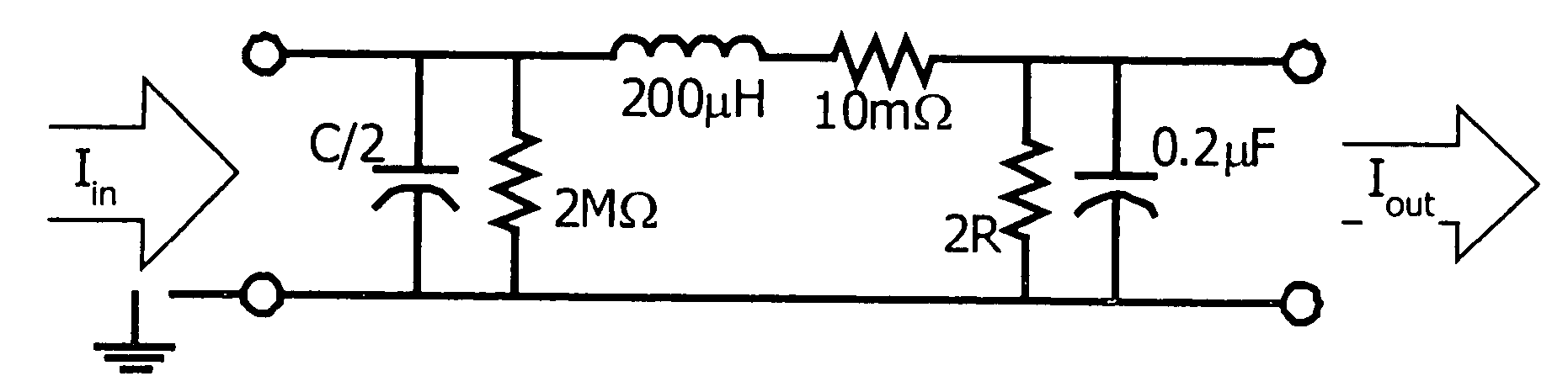
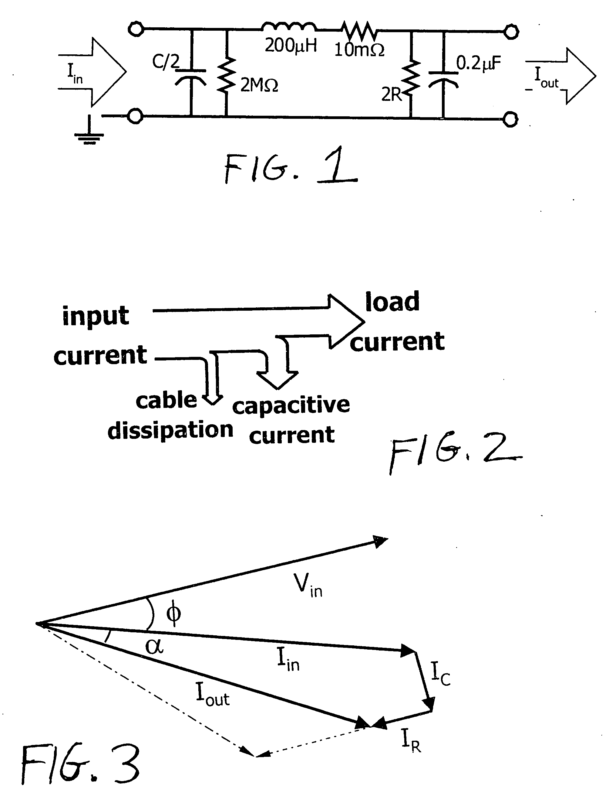
[0016] Referring now to FIGS. 1 and 2, the method and arrangement of the present invention are useful to determine the quality of various types of power lines and power cables during normal operating conditions and any departures from normal operating parameters, e.g. both distribution and transmission lines of various types including underground and overhead installations. For illustrative purposes to assist in the description of the present invention, an illustrative power cable may be represented by a pi model or equivalent circuit as shown in FIG. 1 with representative current components being shown as illustrated in FIG. 2. The illustrative values as shown in FIG. 1 are for an EPR (ethylene propylene rubber) cable, but, except for the “R” parameter, the model and values do not change substantially for power cables of other insulation types. As illustrated in FIG. 2, concerning the current Iin injected at one terminal, some is lost through the capacitance to the sheath, and of t...


PUM


Abstract

An arrangement and method is provided for determining the present condition and/or expected life of electric power lines via the measurement and analysis of the current into and the current out of the electric power line, thus permitting preventive action on electric power lines before problems arise. In this way, any departure from normal operation may also be detected, e.g. such as caused by a high-impedance fault or the like. The phase angle difference between the input and output currents provides a measure of the condition of the line, i.e. specifically, this phase angle shift between the input and output currents increases as the line ages and loss factors increase. Due to the inherent noise in the current signals, in one embodiment the phase angle shift is measured via a cross-correlation between the input and output current signals to provide the measured phase angle. This phase angle is compared to that of acceptable lines and a determination is then made as to the condition or quality of the measured line. Where the signals are extremely noisy, an auto-correlation process is carried out on one of the current signals to provide an error factor that is a measure of the possible error in the cross-correlation process. This error factor is then subtracted from the phase shift as measured in the correlation process to provide a more realistic estimate of the phase angle shift between the input and output currents.

Description

[0001] This application is a continuation of Application No. PCT / US0318639 filed on Jun. 12, 2003 which is a continuation of and claims the benefit of U.S. Provisional Application Nos. 60 / 390,310 filed Jun. 21, 2002 and 60 / 390,949 filed Jun. 24, 2002.BACKGROUND OF THE INVENTION [0002] 1. Field of the Invention [0003] The present invention relates generally to methods and arrangements for determining the present condition and / or expected life of electric power lines via the measurement and analysis of the current into and the current out of the electric power line, thus permitting preventive action on electric power lines before problems arise. [0004] 2. Description of Related Art [0005] Various testing and measurement techniques are known for testing the condition of power cables and transmission lines. For example, U.S. Pat. Nos. 6,088,658 and 6,192,317 are directed to the use of statistical techniques including histograms and trend analysis on partial discharge measurements to eva...

Claims


Application Information

Patent Timeline
IPC IPC(8): G01R31/02G01R31/08G01R31/12
CPCG01R31/021G01R31/12G01R31/08G01R31/58
Inventor ENNIS, MICHAEL G.SATPATHI, DEBASHIS
Owner ENNIS MICHAEL G
Why Eureka
Try Eureka