Waste liquid collecting method, liquid injecting apparatus and cartridge set

Inactive Publication Date: 2005-09-29
SEIKO EPSON CORP
View PDF2 Cites 17 Cited by
  • Summary
  • Abstract
  • Description
  • Claims
  • Application Information

AI Technical Summary

Benefits of technology

[0006] The invention has been made in consideration of the problems and has an object to provide a waste liquid collecting metho

Problems solved by technology

As a result, a waste ink introducing chamber is filled with the air so that the waste ink cannot be collected any more irrespective of the insufficient collection of the waste

Method used


Image

  • Waste liquid collecting method, liquid injecting apparatus and cartridge set
  • Waste liquid collecting method, liquid injecting apparatus and cartridge set
  • Waste liquid collecting method, liquid injecting apparatus and cartridge set

Examples


Example

[0070] A first embodiment carrying out the invention will be described below with reference to FIGS. 1 to 6.

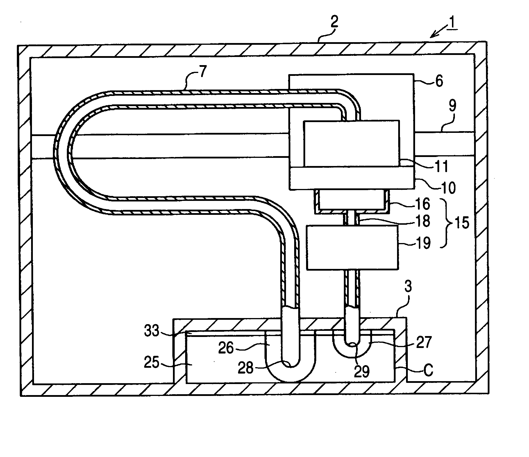
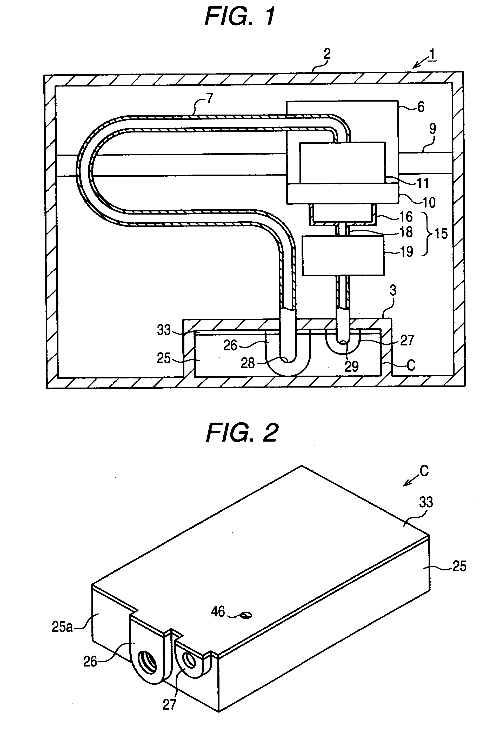
[0071]FIG. 1 is a conceptual view showing a printer according to the embodiment.

[0072] As shown in FIG. 1, a printer 1 to be a liquid injecting apparatus comprises a cover 2, and a cartridge holder 3 is formed in the lower part of the cover 2. An ink cartridge C to be a liquid housing is removably provided in the cartridge holder 3. The ink cartridge C can accommodate an ink to be a liquid, and furthermore, can store a waste ink to be a waste liquid, details of which will be described below.

[0073] The printer 1 comprises a guide member 9, and the guide member 9 is provided over a pair of frames in the cover 2. A carriage 6 is inserted in and supported on the guide member 9 movably in the axial direction of the guide member 9. The carriage 6 is connected to a carriage motor (not shown) through a timing belt (not shown) and is reciprocated along the guide member 9 by the driv...

Example

Second Embodiment

[0107] Next, a second embodiment carrying out the invention will be described with reference to FIG. 7. One of features according to the embodiment is that a plurality of ink cartridges C described in the first embodiment is connected. In the following embodiment, the same portions as those in the first embodiment have the same reference numerals and detailed description thereof will be omitted.

[0108]FIG. 7 is a conceptual view showing a waste liquid collecting system in which a plurality of ink cartridges is connected.

[0109] In the embodiment, the waste liquid collecting system comprises ink cartridges C1, C2, C3, C4, C5 and C6 corresponding to six ink colors (black, cyan, magenta, yellow, light cyan and light magenta), for example. Moreover, the waste liquid collecting system comprises a maintenance mechanism 15. In the case in which the description is to be given without the distinction of these ink cartridges C1 to C6 from each other, they will be hereinafter...

Example

Third Embodiment

[0122] A third embodiment carrying out the invention will be described below with reference to FIGS. 8 to 16. FIG. 8 is a perspective view showing a printer 1 to be a liquid injecting apparatus, FIG. 9 is a perspective view showing the main part of the printer 1, FIG. 10 is a typical view for explaining the cleaning operation of the printer 1, and FIG. 11 is an explanatory view showing the flow of an ink to be a liquid and a waste ink to be a waste liquid for a cartridge C. The same portions as those in the first and second embodiments have the same reference numerals and detailed description thereof will be omitted. One of features according to the embodiment is that a flow path resistance to the waste liquid in at least one of the ink cartridges C attached to the printer 1 is set to be lower than a flow path resistance for the waste liquid in another ink cartridge.

[0123] As shown in FIG. 8, the printer 1 comprises a cartridge holder 3 on the upper surface of a co...


PUM


Abstract

A printer includes a recording head and a maintenance mechanism for sucking an ink in the recording head. A plurality of cartridges to be attached to the printer includes a first housing portion for storing an ink to be supplied to the recording head and a second housing portion for storing a waste ink discharged from the maintenance mechanism. In a first one of the cartridges, the flow path resistance of a cartridge side flow path from a waste ink introducing portion to an air communicating hole for discharging air in a waste ink reservoir portion to an outside through the waste ink reservoir portion is lower than the flow path resistance of each of the cartridge side flow paths of the other cartridges.

Description

BACKGROUND OF THE INVENTION [0001] The present invention relates to a waste liquid collecting method, a liquid injecting apparatus and a cartridge set. [0002] An ink jet type recording apparatus (hereinafter referred to as a printer) has been known as a liquid injecting apparatus for discharging a liquid from a liquid injecting head to a target. A maintenance mechanism is usually provided on a non-printing region in the printer. The maintenance mechanism carries out suction cleaning for sucking a thickened ink and air bubbles from a nozzle in order to prevent the nozzle clogging of a recording head to be a liquid injecting head. [0003] A waste ink sucked from the recording head by the maintenance mechanism is fed to a waste ink tank provided in the printer. Alternatively, the waste ink is fed to an ink cartridge including an ink reservoir portion accommodating an unused ink and a waste ink reservoir portion in some cases (for example, see JP-A-2003-118144). In these cases, the waste...

Claims


Application Information

Patent Timeline
IPC IPC(8): B41J2/165B41J2/17B41J2/175
CPCB41J2/17506B41J2/1721
Inventor KIMURA, HITOTOSHI
Owner SEIKO EPSON CORP
Why Eureka
Try Eureka