Rotational driving apparatus and camera using the rotational driving apparatus

a driving apparatus and rotating technology, applied in the direction of printers, camera focusing arrangements, gearing, etc., can solve the problems of worm backlash, inability to apply adequate pressing force to the worm, worm backlash, etc., and achieve the effect of stable pressing for

Inactive Publication Date: 2005-09-29
FUJI PHOTO OPTICAL CO LTD
View PDF3 Cites 34 Cited by
  • Summary
  • Abstract
  • Description
  • Claims
  • Application Information

AI Technical Summary

Benefits of technology

[0016] According to the invention, the tip end face of the worm comprises a recess having a hemispherical shape. Therefore, the pressing member which has a

Problems solved by technology

There is a possibility that the press fitting is loosened as a result of a long term use and the worm moves on the output shaft to slip off from the output shaft.
In the worm supporting structure disclosed in JP-A-2001-309610, however, the pressing force which is applied to the worm by the pressing member cannot be adjusted, and henc

Method used


Image

  • Rotational driving apparatus and camera using the rotational driving apparatus
  • Rotational driving apparatus and camera using the rotational driving apparatus
  • Rotational driving apparatus and camera using the rotational driving apparatus

Examples


Embodiment Construction

[0024] Hereinafter, the best mode for carrying out the rotational driving apparatus of the invention, and a camera using the rotational driving apparatus will be described in detail with reference to the accompanying drawings.

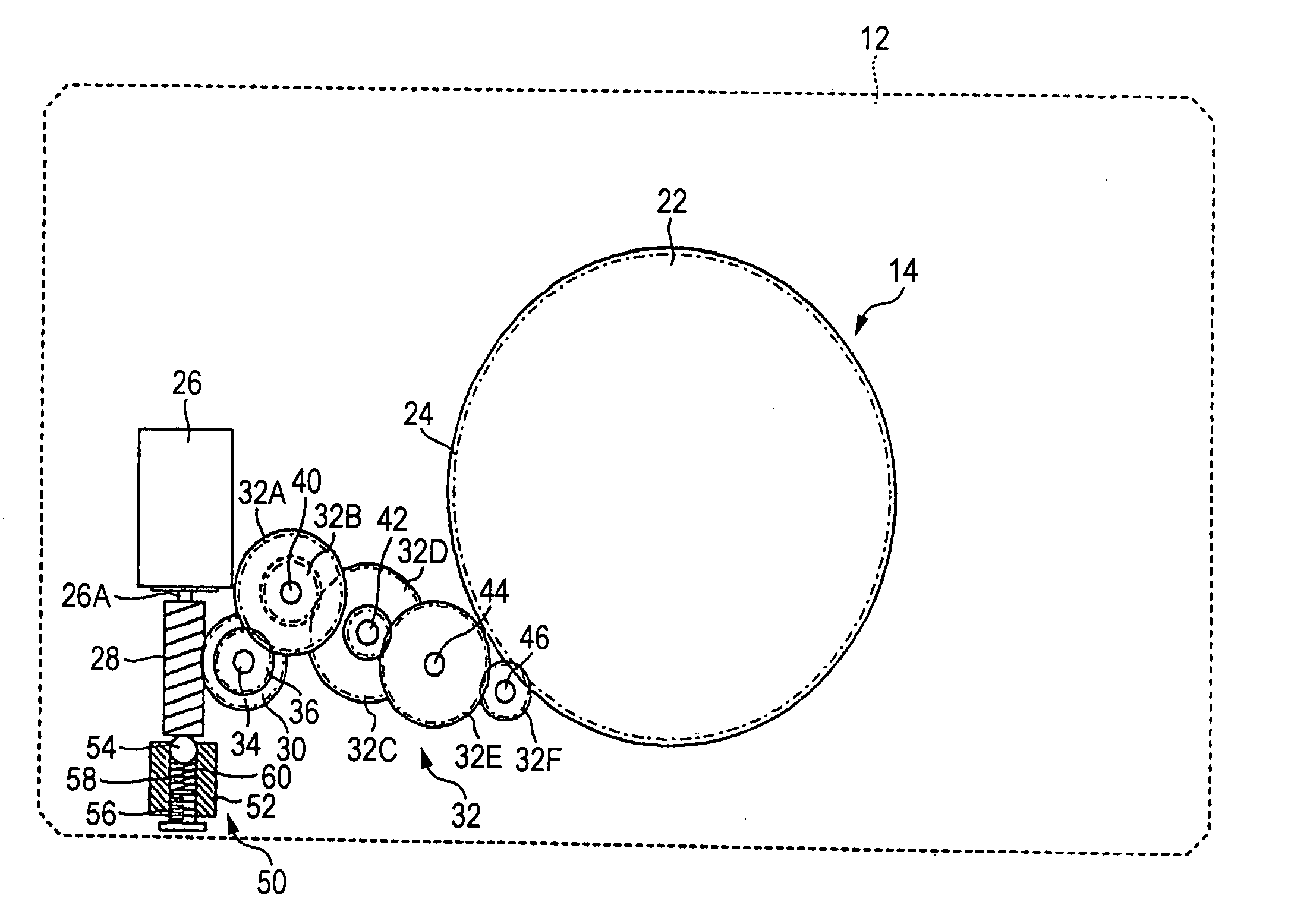
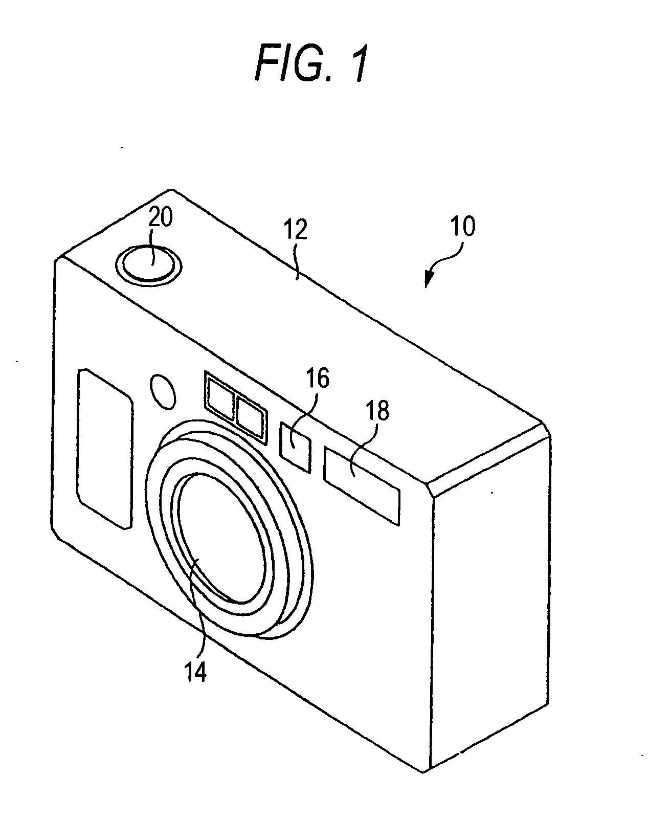
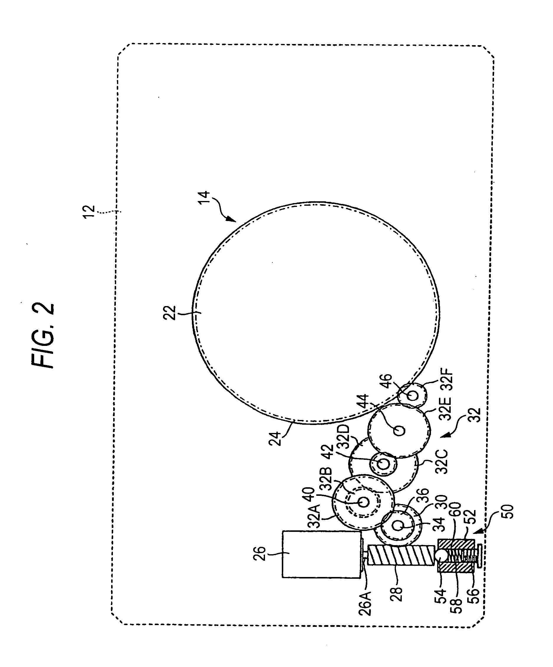
[0025]FIG. 1 is a perspective view showing the external configuration of a camera using the rotational driving apparatus of the invention. The camera 10 is a film camera which uses a 135 film. An imaging lens 14, a finder window 16, a strobe flash 18, and the like are disposed on the front face of the camera body 12. A shutter release button 20 is disposed on the upper face of the camera body 12, and a power switch, a zoom button, and the like are disposed on the back face of the camera body 12 which is not shown.

[0026] The imaging lens 14 is configured by a collapsible type zoom lens. When the power supply of the camera 10 is turned ON, the lens advances from the front face of the camera body 12, and then stops at the wide-angle end. When the power supply of...


PUM


Abstract

A rotational driving apparatus which comprises a motor, a worm pressingly fitted to an output shaft of the motor, and a worm wheel meshing with the worm, to output rotation of the motor from the worm wheel via the worm, the apparatus comprising: a support member placed with forming a gap with respect to a tip end of the worm, the support member comprising a through hole positioned on a same axis as the worm; a pressing member that is inserted into the through hole, and protrudes from a tip end of the through hole to butt against a tip end face of the worm; a plug member fitted into the through hole to close the through hole, in which its fitting degree into the through hole is adjustable; and an urging member interposed between the pressing member and the plug member to urge the pressing member toward the worm.

Description

BACKGROUND OF THE INVENTION [0001] 1. Field of the Invention [0002] The present invention relates to a rotational driving apparatus and a camera using the rotational driving apparatus, and more particularly to a rotational driving apparatus to be used as a rotational driving source for a lens device in which a lens is moved forward and backward along the optical axis by a cam mechanism, and a camera using the rotational driving apparatus. [0003] 2. Description of the Related Art [0004] In the case where rotation of a motor is to be decelerated at once, for example, a worm gear is usually used. A worm gear consists of a worm and a worm wheel. In the case where rotation of a motor is to be decelerated at once, a worm is previously attached to an output shaft of the motor, and rotation of the motor is transmitted to a worm wheel which meshes with the worm, thereby immediately decelerating the rotation. [0005] Usually, a worm is attached to an output shaft of the motor by press fitting....

Claims


Application Information

Patent Timeline
IPC IPC(8): G02B7/08F16H1/16G02B7/02G02B7/10G03B17/00G03B17/04H02K7/00H04N5/225
CPCF16H1/16G03B17/04G02B7/102
Inventor MANABE, MITSUOTSUYUKI, KAZUHIRO
Owner FUJI PHOTO OPTICAL CO LTD
Why Eureka
Try Eureka