Transmitted packet replenishment system and transmitted packet replenishing method

a replenishment system and packet technology, applied in data switching networks, frequency-division multiplex, wireless commuication services, etc., can solve the problems of preventing the execution of flow control, difficult to predict the occurrence of handover on each mobile node, and the load on the network becomes very heavy, so as to avoid a packet loss, reduce the process relating, and minimize the use of resources

Inactive Publication Date: 2005-09-29
FUJITSU LTD
View PDF9 Cites 43 Cited by
  • Summary
  • Abstract
  • Description
  • Claims
  • Application Information

AI Technical Summary

Benefits of technology

[0025] The present invention aims at avoiding a loss of a packet in the wireless communications system. The present invention also aims at reducing the process relating to the replenishment of a packet or minimizing the resources used for the replenishment.
[0028] The above-mentioned method can further includes a step of discarding a duplicate packet received in the receiving apparatus. With the step, although duplicate packets are received, it is determined that a packet has been correctly received in an upper layer. Therefore, the packet retransmitting process is avoided in the upper layer in which a packet is processed, thereby suppressing the degradation in throughput.
[0031] In this method, when the intensity of a radio wave is reduced, the packet transmitted from a mobile node is stored in the storage device in the mobile node. When the intensity of a radio wave recovers, the packet transmitted in the past is retrieved from the storage device and transmitted. That is, when the intensity of a radio wave recovers, a packet transmitted during the period when the intensity of a radio wave is degraded is retransmitted. Thus, a loss of a packet caused by the degradation of the intensity of a radio wave can be replenished.

Problems solved by technology

Thus, although the order of the packets received by the delay difference in the wireless network is inverted, a retransmission request is not immediately issued, thereby preventing the execution of the flow control.
However, it is difficult to predict the occurrence of handover on each mobile node.
If it should be possible, the load on the network becomes very heavy.
However, when the transmission of a packet is stopped for any reason other than the handover, there is no opportunity of resuming the transmission of packets.
Therefore, the packet to be transmitted by a mobile node cannot reach a corresponding node.
However, when a packet is lost, it cannot be replenished.

Method used


Image

  • Transmitted packet replenishment system and transmitted packet replenishing method
  • Transmitted packet replenishment system and transmitted packet replenishing method
  • Transmitted packet replenishment system and transmitted packet replenishing method

Examples


first embodiment

[0087] Thus, in the packet replenishing method the transmitted data is stored in the transmitted data holding unit 23 in the mobile node 2. At this time, the data in the radio space between the mobile node 2 and the access router when handover occurs can be lost. Therefore, when handover occurs, the data of the amount specified by the replenishment information management unit 24 is read from the transmitted data holding unit 23 and retransmitted. Thus, a packet loss can be suppressed even when handover occurs.

[0088] In the second embodiment, the receiving terminal has the function of discarding a received duplicate packet. The transmitting terminal side is similar to that in the first embodiment. Therefore, the explanation is omitted here, and the operation and the effect of a receiving terminal are explained below.

[0089]FIG. 8 shows the principle of the receiving terminal according to the present invention. A receiving terminal comprises receiving unit 51 for receiving data trans...

second embodiment

[0094] Thus, when the same packets are received as duplicate packets in the packet replenishing method the duplicate detection unit 52 and the discard unit 53 perform the discarding process. Therefore, although the same packets are received as duplicate packets, it is determined that packets are normally received in the upper layer. Therefore, the flow control which is a retransmitting procedure is not performed in the upper layer, thereby efficiently performing communications.

[0095] In the present embodiment, a receiving terminal determines whether or not the same packets have been received as duplicate packets according to the flag assigned to a transmitted packet. FIG. 10 is an explanatory view of the method of determining a duplicate packet received by a receiving terminal using a flag assigned to a transmitted packet. The packet replenishing method according to the present embodiment is explained below by mainly describing the point different from the second embodiment.

[0096]...

fourth embodiment

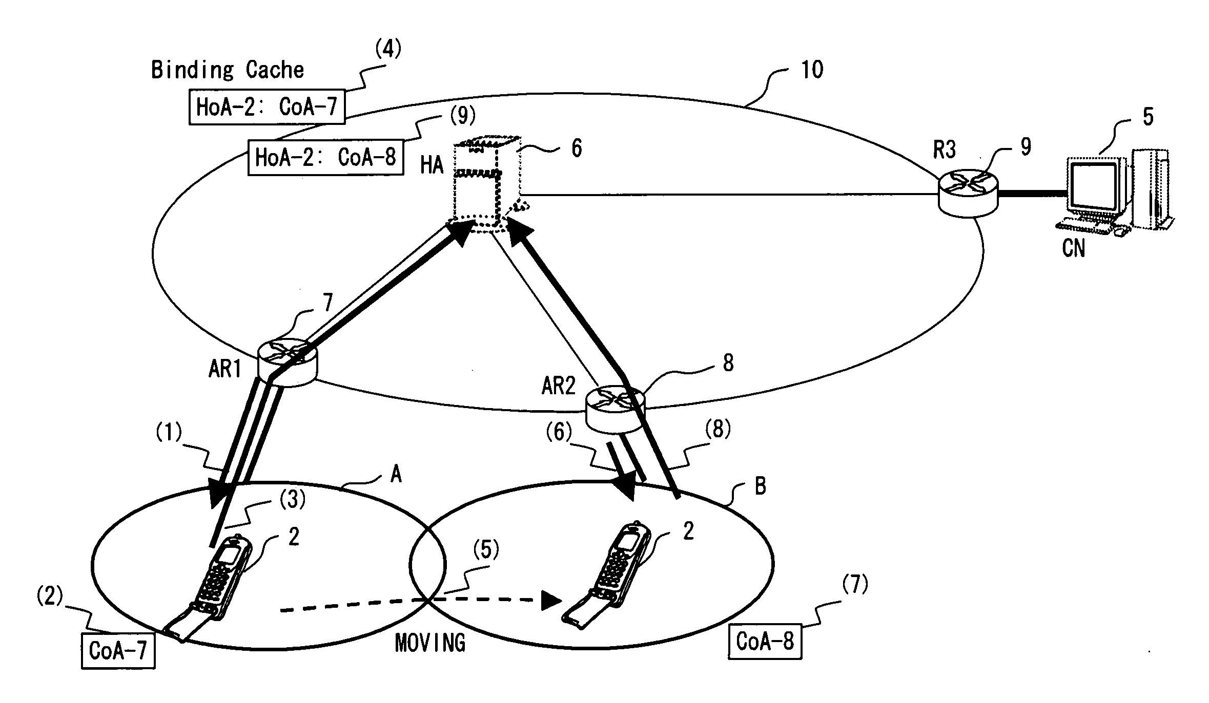
[0101]FIG. 14 is an explanatory view of the packet replenishing method according to the Since the processes up to the process of the mobile node 2 position-registered as belonging to the wireless network A are similar to those in the above-mentioned embodiment, the explanation is omitted here. (5) refers to data to be transmitted from the mobile node 2 to the corresponding node 5, and the numbers 1 through 20 in (5) respectively indicate the packets having the data numbers 1 through 20.

[0102] When the mobile node 2 transmits packets in the ascending order of the data numbers, it first sequentially stores packets in the transmitted data holding unit 23 shown in FIG. 6, and then transmits them. (6) shown in FIG. 14 indicates the status of storing the packets up to the packet having the data number 15 in the transmitted data holding unit 23. In (7), the transmission control unit 21 shown in FIG. 6 sequentially transmits the packets stored in the transmitted data holding unit 23 in the...


PUM


Abstract

In a mobile IP network, a mobile node transmits data to a corresponding node. The transmitted data is stored in a transmitted data holding unit in the mobile node. The mobile node manages replenishment information indicating an operation relating to the retransmission of a packet. The mobile node retrieves a packet specified according to the replenishment information from the transmitted data holding unit when handover occurs, and transmits (retransmits) the packet.

Description

BACKGROUND OF THE INVENTION [0001] 1. Field of the Invention [0002] The present invention relates to a packet replenishing method used when a packet is transmitted or received over a wireless communications network, and a mobile node, a relay node, and a receiving terminal used in the wireless communications network. [0003] 2. Description of the Related Art [0004]FIG. 1 shows an example of the configuration of an existing IPv6 network. A home agent (mobile support device, HA) 6, access routers 7 and 8, and a router 9 are connected to the Internet 10. A mobile node (MN) 2 transmits data to a corresponding node CN) 5. The mobile node 2 belongs to a wireless network A and communicates with the corresponding node 5 through the access router 7. After the mobile node 2 transfers to belong to a wireless network B, it performs communications through the access router 8. [0005]FIG. 2 is an explanatory view showing an operation performed when handover occurs. First in (1), when the mobile nod...

Claims


Application Information

Patent Timeline
Patent Type & Authority Applications(United States)
IPC IPC(8): H04H1/00H04L1/18H04L12/70H04L12/801H04L12/911H04L29/06H04W28/00H04W28/04H04W36/00H04W36/02H04W36/08H04W80/04H04W80/06
CPCH04L1/1809H04L1/1854H04L1/1874H04W80/06H04W36/0011H04W36/02H04W80/04H04L1/1887
Inventor MATSUMOTO, YUJI
Owner FUJITSU LTD
Why Eureka
Try Eureka