Kinetic spray nozzle system design

a nozzle system and nozzle technology, applied in the direction of superimposed coating process, liquid/solution decomposition chemical coating, manufacturing tools, etc., can solve the problems of not being able to successfully spray particle sizes and material compositions, being more difficult to accelerate large particles, and being difficult to achieve the effect of large particle siz

a nozzle system and nozzle technology, applied in the direction of superimposed coating process, liquid/solution decomposition chemical coating, manufacturing tools, etc., can solve the problems of not being able to successfully spray particle sizes and material compositions, being more difficult to accelerate large particles, and being difficult to achieve the effect of large particle siz

US20050214474A1Inactive Publication Date: 2005-09-29DELPHI TECH INC

Image

  • Kinetic spray nozzle system design
  • Kinetic spray nozzle system design
  • Kinetic spray nozzle system design

Examples


Embodiment Construction

[0028] The present invention comprises a dramatic improvement to the kinetic spray process and nozzle system as generally described in U.S. Pat. Nos. 6,139,913, 6,283,386 and the article by Van Steenkiste, et al. entitled ā€œKinetic Spray Coatingsā€ published in Surface and Coatings Technology Volume III, Pages 62-72, Jan. 10, 1999, all of which are herein incorporated by reference.

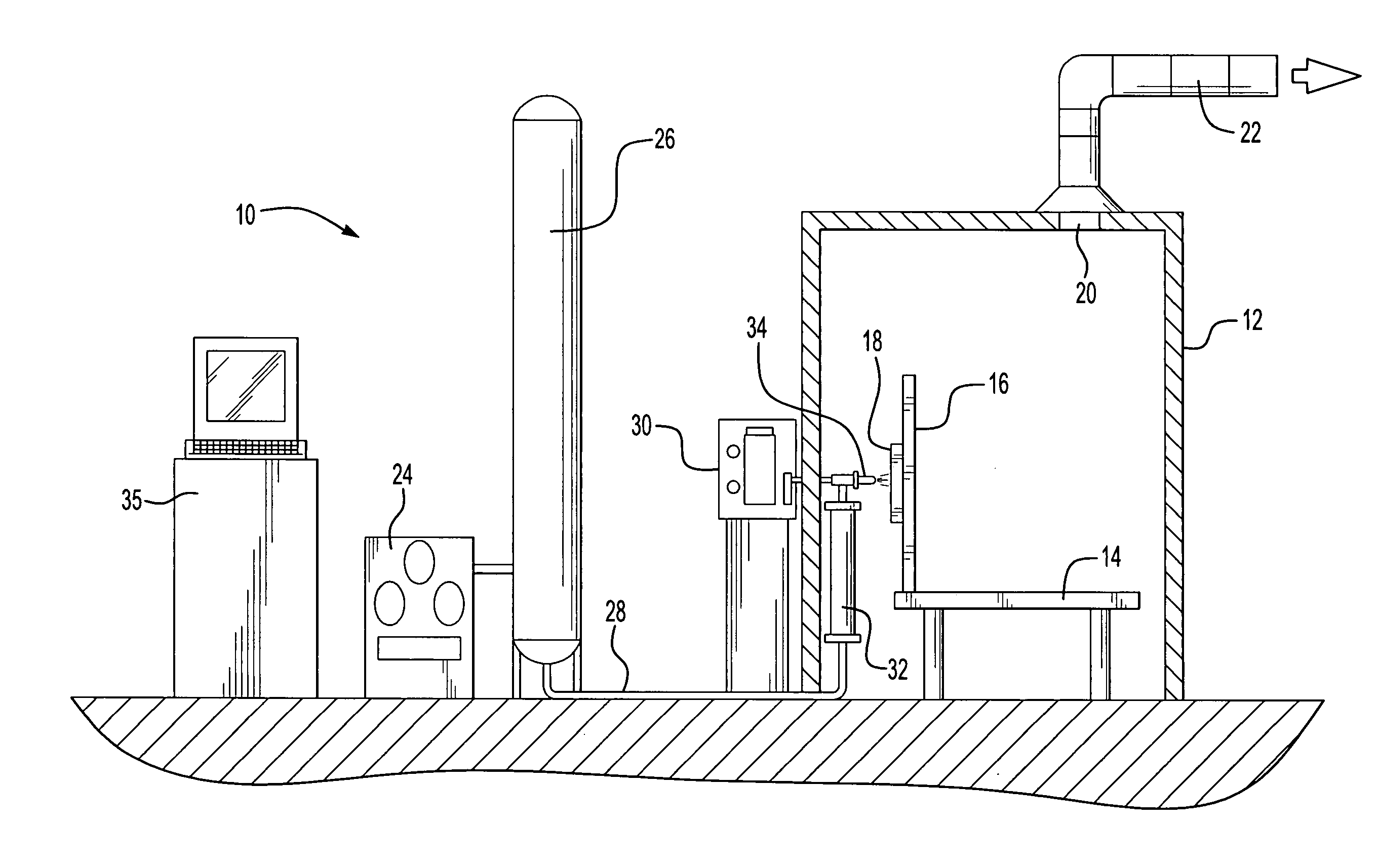
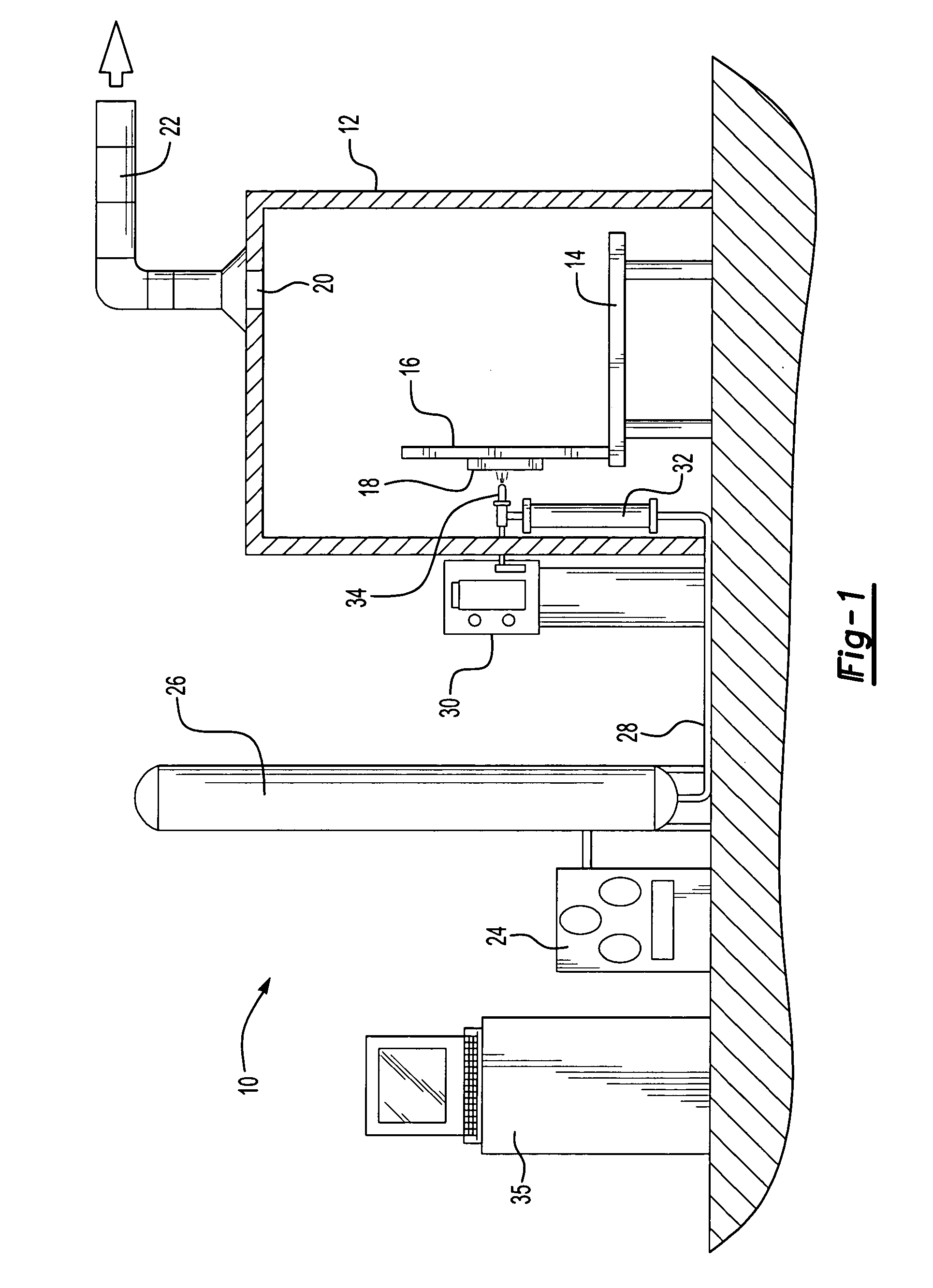
[0029] Referring first to FIG. 1, a kinetic spray system for use of a nozzle designed according to the present invention is generally shown at 10. System 10 includes an enclosure 12 in which a support table 14 or other support means is located. A mounting panel 16 fixed to the table 14 supports a work holder 18 capable of movement in three dimensions and able to support a suitable workpiece formed of a substrate material to be coated. The enclosure 12 includes surrounding walls having at least one air inlet, not shown, and an air outlet 20 connected by a suitable exhaust conduit 22 to a dust collector, not ...


PUM

PropertyMeasurementUnit
lengthaaaaaaaaaa
diameteraaaaaaaaaa
pressureaaaaaaaaaa

Abstract

An improved kinetic spray nozzle system is disclosed in addition to improved methods for injection particle powders into a nozzle. Utilization of the nozzle enables one to dramatically increase the deposition efficiency of a variety of particles using a kinetic process. The improved nozzle includes a powder / gas conditioning chamber that increases the particle residence time within the nozzle enabling one to achieve higher particle temperatures prior to their acceleration in the supersonic portion of the kinetic spray nozzle.

Description

TECHNICAL FIELD [0001] The present invention relates to spraying of powders by a kinetic spray process, and particularly, to an improved nozzle system for a kinetic spray system. INCORPORATION BY REFERENCE [0002] U.S. Pat. No. 6,139,913, ā€œKinetic Spray Coating Method and Apparatus,ā€ and U.S. Pat. No. 6,283,386 ā€œKinetic Spray Coating Apparatusā€ are incorporated by reference herein. BACKGROUND OF THE INVENTION [0003] The prior art for kinetic spray systems generally discloses a kinetic spray system having a nozzle system that includes a gas / powder exchange chamber directly connected to a converging diverging deLaval type supersonic nozzle. The system introduces a stream of powder particles under positive pressure into the exchange chamber. The powder gas, which is used to drive the powder to the exchanger chamber, is not heated to prevent powder from clogging the powder pipeline. A heated main gas is also introduced into the exchange chamber under a pressure, which is set lower than t...

Claims


Application Information

Patent Timeline
29 Sep 2005
Publication
US20050214474A1
IPC
B05B7/14; C23C24/04
CPC
C23C24/04; B05B7/1486
Inventors
HAN, TAEYOUNG; ZHAO, ZHIBO