
White electroluminescent polymeric material & preparation thereof

a polymeric material and electroluminescent technology, applied in the field of preparation thereof, can solve the problems of difficult to obtain stable white light device, poor performance sharp voltage-dependent color of white light polymeric device, etc., and achieve stable white electroluminescent polymeric material system and high efficiency

Active Publication Date: 2005-09-29
CHANGCHUN INST OF APPLIED CHEMISTRY - CHINESE ACAD OF SCI
View PDF1 Cites 20 Cited by
  • Summary
  • Abstract
  • Description
  • Claims
  • Application Information

AI Technical Summary

Benefits of technology

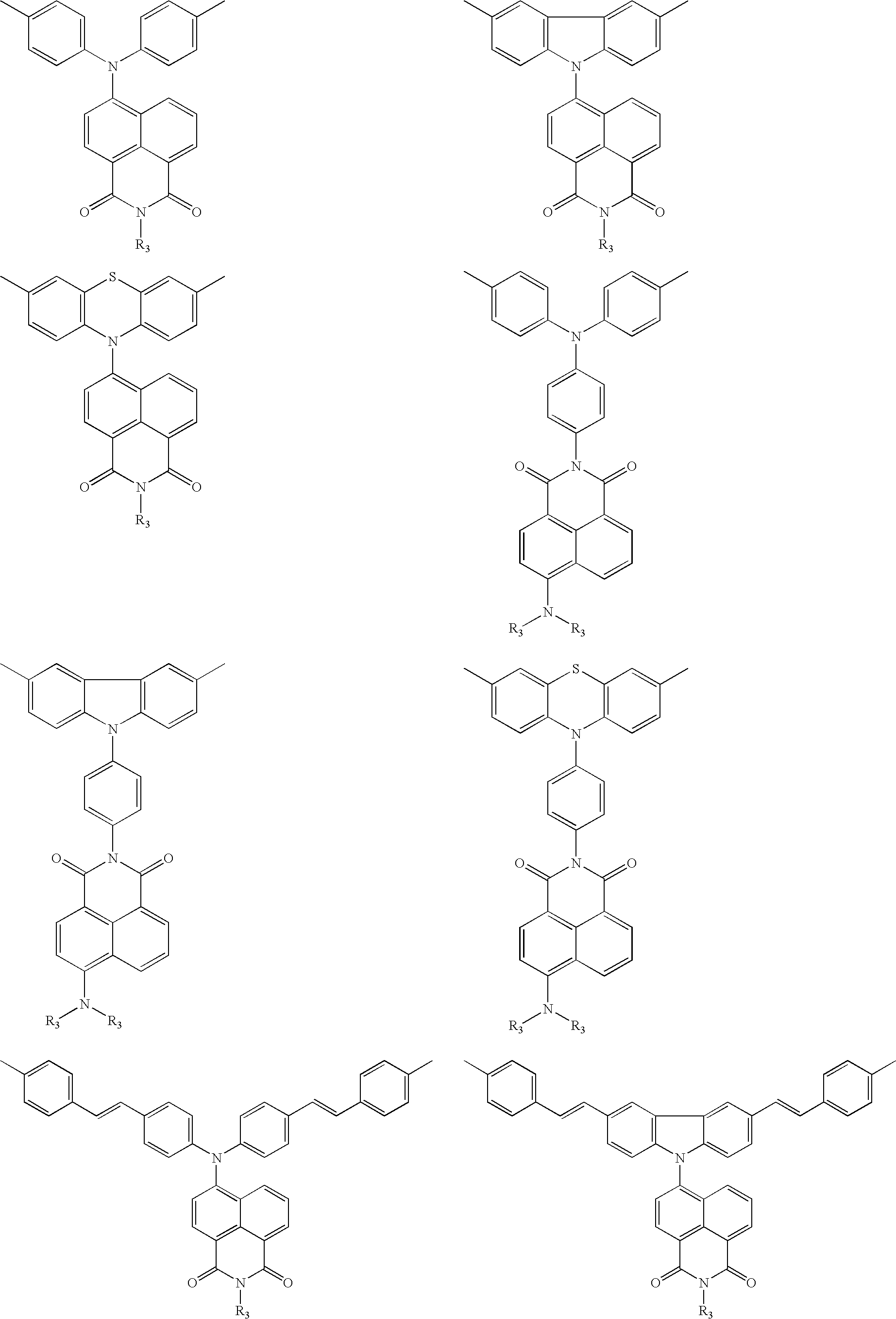
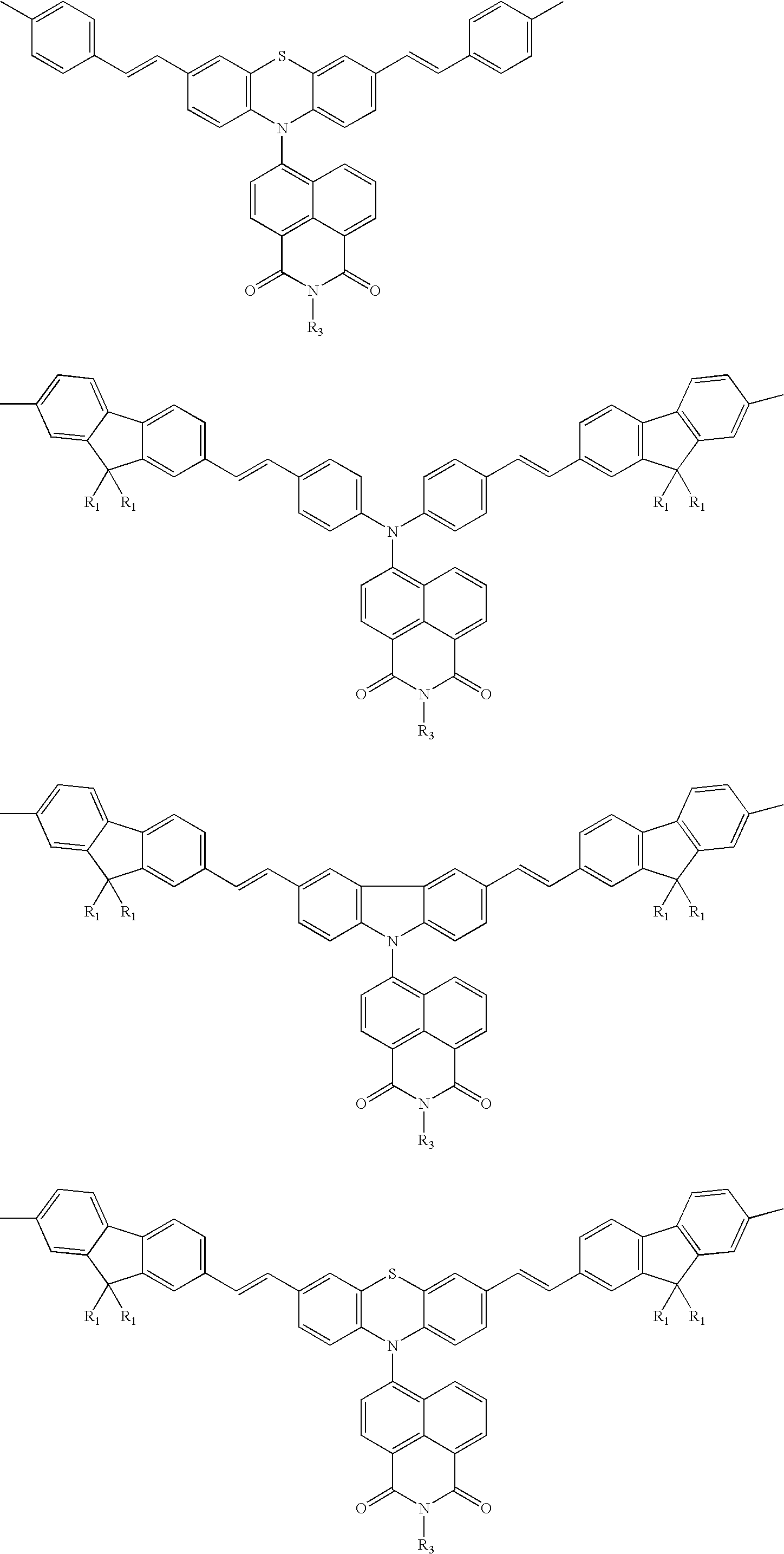
[0005] The inventors of the present invention find that white light emission can be achieved by regulating the relative luminous intensities of blue- and orange-light emitting units located in a single polymer molecule.

Problems solved by technology

By contrast, there is a larger gap between every performance index of white light polymeric device and practical requirement.
But the system has the following disadvantages: the obvious phase separation between polymer and polymer results in the voltage-dependence of white light emission, and thus a stable white light device is difficult to be obtained.
For the single polymeric w

Method used


Image

  • White electroluminescent polymeric material & preparation thereof
  • White electroluminescent polymeric material & preparation thereof
  • White electroluminescent polymeric material & preparation thereof

Examples


example 1

Synthesizing of 4-bromo-9-(4-t-butylphenyl)-1,8-naphthalimide

[0122] Under the protection of N2 gas, 4-bromo-1,8-naphthalic anhydride (10.0 g, 36.2 mmol), p-t-butyl aniline (6.0 g, 40.1 mmol) were added into a reacting flask containing 120 ml of acetic acid as a solvent. After reacting while magnetic stirring at 130° C. for 10 hr, the reaction product was poured into water, filtered, washed repeatedly, and separated by column chromatography. 8.10 g (yield 55%) of a white solid 4-bromo-9-(4-t-butylphenyl)-1,8-naphthalimide was obtained. 1H NMR (CDCl3, 300 MHz) δ 8.68(d, 1H), 8.59(d, 1H), 8.43(d, 1H), 8.04(d, 1H),7.86 (t, 1H), 7.56 (d, 2H), 7.23 (d, 2H), 1.38 (s, 9H).

example 2

Synthesizing of 4-N,N-diphenyl-9-(4-t-butylphenyl)-1,8-naphthalimide

[0123] Under the protection of N2 gas, 3 ml of DMPU solvent was added into a mixture of 4-bromo-9-(4-t-butylphenyl)-1,8-naphthalimide (4.48 g, 11.0 mmol), diphenylamine (1.69 g, 10.0 mmol), anhydrous potassium carbonate (1.53 g, 11.0 mmol), cuprous iodide (0.096 g, 0.50 mmol), and 18-crown-6 (0.13 g, 0.50 mmol). After reacting while magnetic stirring at 190° C. for 20 hr, the reaction product was extracted with dichloromethane, acid washed, ammonia liquor washed, water washed repeatedly, and separated by column chromatography. 1.74 g (yield 35%) of an orange red solid 4-N,N-phenyl-9-(4-t-butylphenyl)-1,8-naphthalimide was obtained.

[0124]1H NMR (CDCl3, 300 MHz) δ 8.61(d, 1H), 8.54(d, 1H), 8.22(d, 1H), 7.57-7.50 (m, 3H), 7.40 (d, 1H).7.30-7.22(d, 6H),7.11-7.04 (m, 6H), 1.38 (s, 9H).

example 3

Synthesizing of 4-N,N-di(4-bromophenyl)-9-(4-t-butylphenyl)-1,8-naphthalimide

[0125] 4-N,N-diphenyl-9-(4-t-butylphenyl)-1,8-naphthalimide (1.49 g, 3.0 mmol), tetra-n-butylammonium tribromide (3.16 g, 6.6 mmol) were dissolved in 50 ml of dichloromethane. After reacting at room temperature for 10 min, the reaction product was poured into water. The organic layer, after washing repeatedly, was separated by column chromatography. 1.91 g (yield 97%) of an orange red solid (pure intermediate product)-4-N,N-di(4-bromophenyl)-9-(4-t-butylphenyl)-1,8-naphthalimide was obtained. 1H NMR (CDCl3, 300 MHz) δ 8.60(d, 1H), 8.55(t, 1H), 8.16(d, 1H), 7.60(d, 1H), 7.56(d, 2H), 7.42-7.37 (m, 5H).7.22(d,2H), 6.90(d,4H), 1.38 (s, 9H).


PUM

PropertyMeasurementUnit
Temperatureaaaaaaaaaa

Abstract

This invention relates to a white electroluminescent polymeric material and preparation thereof. Based on the physical idea that white light emission can be achieved by regulating the relative luminous intensities of blue- and orange-light emitting units located in a single polymer molecule, the present invention provides three types (main chain type, pendant chain type, and terminal group type) of high efficiency and stable white electroluminescent polymeric material systems.

Description

TECHNICAL FIELD [0001] This invention relates to a white electroluminescent polymeric material and preparation thereof. BACKGROUND ART [0002] Since the electroluminescence of poly(p-phenylene vinylene) (PPV) was first reported by Burroughs et al, Cambridge Univ. U.K. in 1990, the polymeric electroluminescent material and manufacturing device thereof has been extensively concerned and investigated by the research and industry circles due to its prominent characteristics of simple process, easy to achieve large screen display and flexible display etc. At present, some typical blue-, green- and red-light polymeric luminescent material systems, such as poly(p-phenylene) (PPP), poly(alkylfluorene) (PAF), poly(phenylvinylene) (PPV), polythiophene (PTh) etc, have been developed. All the performance indexes of the monochromatic light polymeric electroluminescent device made of them can fulfill practical requirements. By contrast, there is a larger gap between every performance index of whit...

Claims


Application Information

Patent Timeline
IPC IPC(8): B32B19/00C07D401/04C07D417/04C09K11/06H01L51/00H01L51/50
CPCC07D401/04C07D417/04C09K11/06C09K2211/1416C09K2211/1466Y02B20/181C09K2211/1483H01L51/0039H01L51/0043H01L51/5036C09K2211/1475Y10S428/917Y02B20/00H10K85/115H10K85/151H10K50/125
Inventor WANG, LIXIANGTU, GUOLICAO, JIANXINLIU, JUNMA, DONGGEJING, XIA BINWANG, FOSONG
Owner CHANGCHUN INST OF APPLIED CHEMISTRY - CHINESE ACAD OF SCI
Learn More