

Microbattery and systems using microbattery
- Summary
- Abstract
- Description
- Claims
- Application Information
AI Technical Summary
Benefits of technology
Problems solved by technology
Method used
Image

Examples
Embodiment Construction
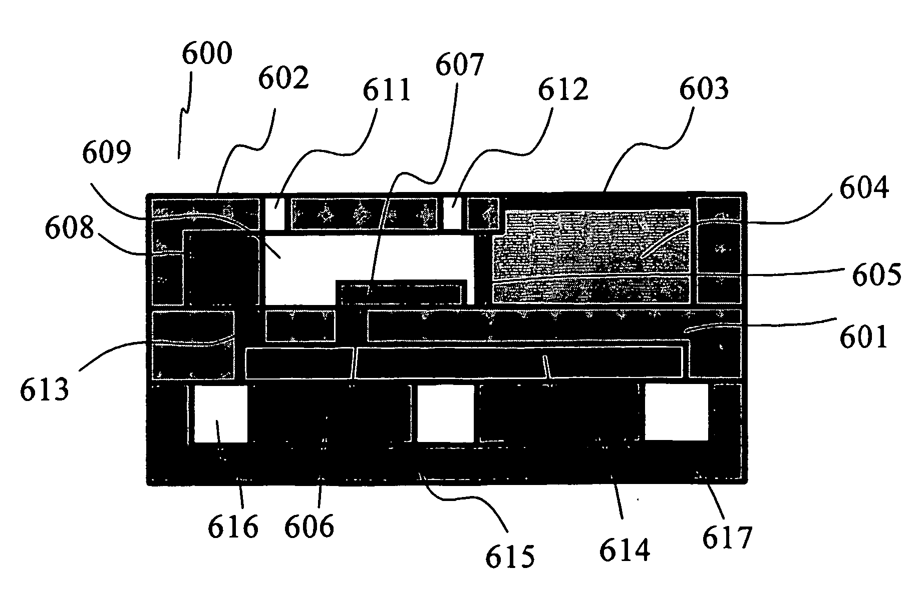
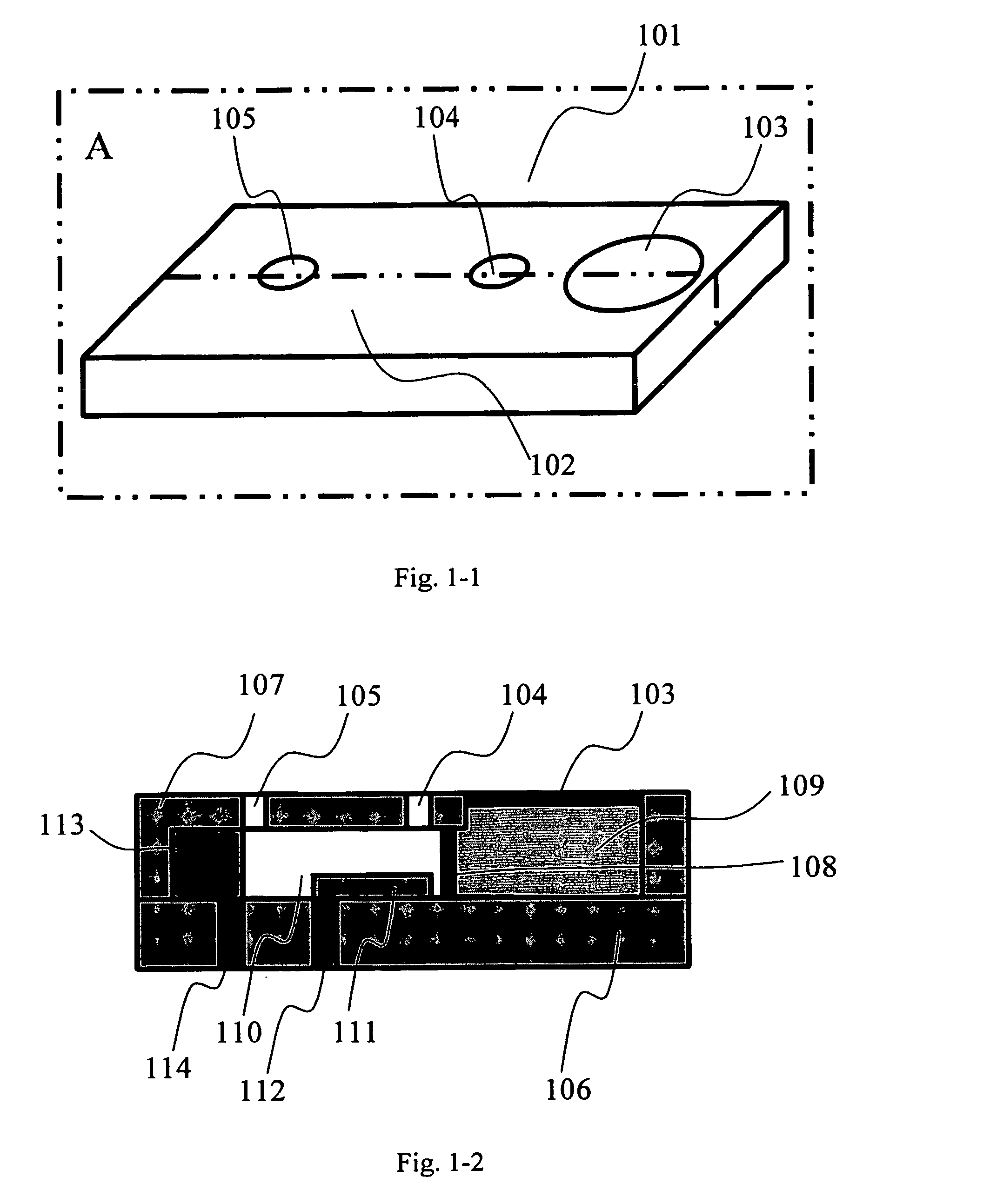
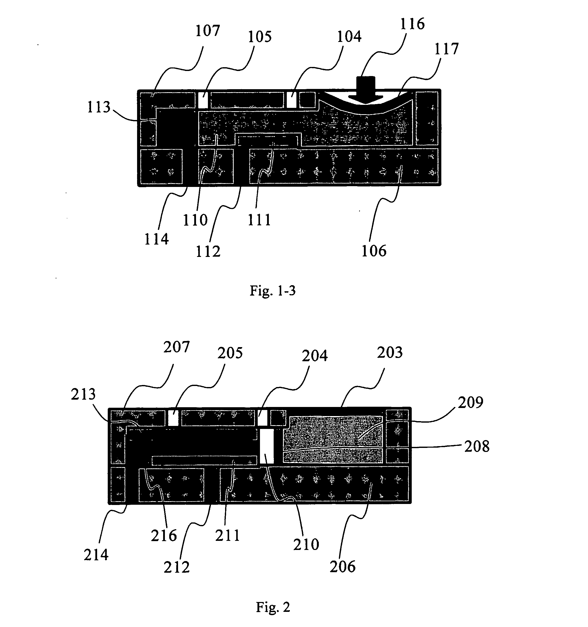
[0069]FIGS. 1-1, 1-2, and 1-3 show perspective view, side view, and working principle of a microbattery 101 embodying of the invention. In a perspective view FIG. 1-1, microbattery 101 consists of activation button 103 and several air hole 104 and 105 on a body 102. FIG. 1-2 is a side view of a microbattery along cross section A of FIG. 1-1 to show the microbattery detail. The microbattery 101 consists of a upper plate 107 mounted on the substrate 106, an activation button 103 on the upper plate 107, a breaking means 108 such as a membrane placed between the upper plate 107 and the substrate 106 that is used to store an electrolyte 109 and is torn away when it is needed to break, a cavity 110 between the upper plate 107 and the substrate 106, an electron collector 111 placed in the cavity 110 on the substrate 106, an anode 113 supplying electrons after reaction to the electrolyte 109, electrical conductors 112 and 114 for outside circuit to contact the electron collector 111 and the...
PUM
 Abstract
Description
Claims
Application Information