
Steering device

a steering device and steering technology, applied in the direction of steering initiation, vessel construction, instruments, etc., can solve the problems of generating deterioration of so as to improve the stability in the vehicle motion

Inactive Publication Date: 2005-09-29
JTEKT CORP +1
View PDF4 Cites 23 Cited by
  • Summary
  • Abstract
  • Description
  • Claims
  • Application Information

AI Technical Summary

Benefits of technology

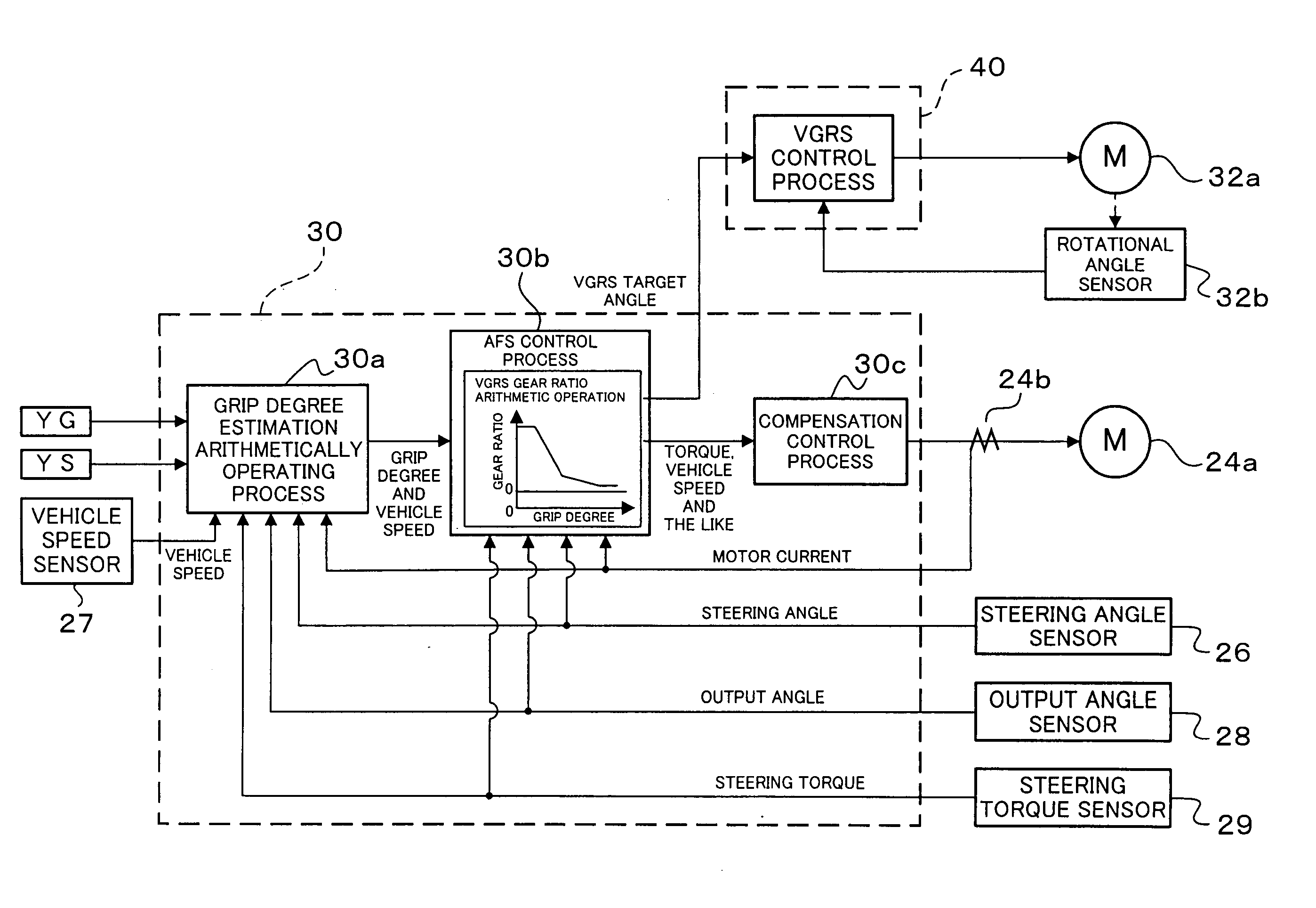
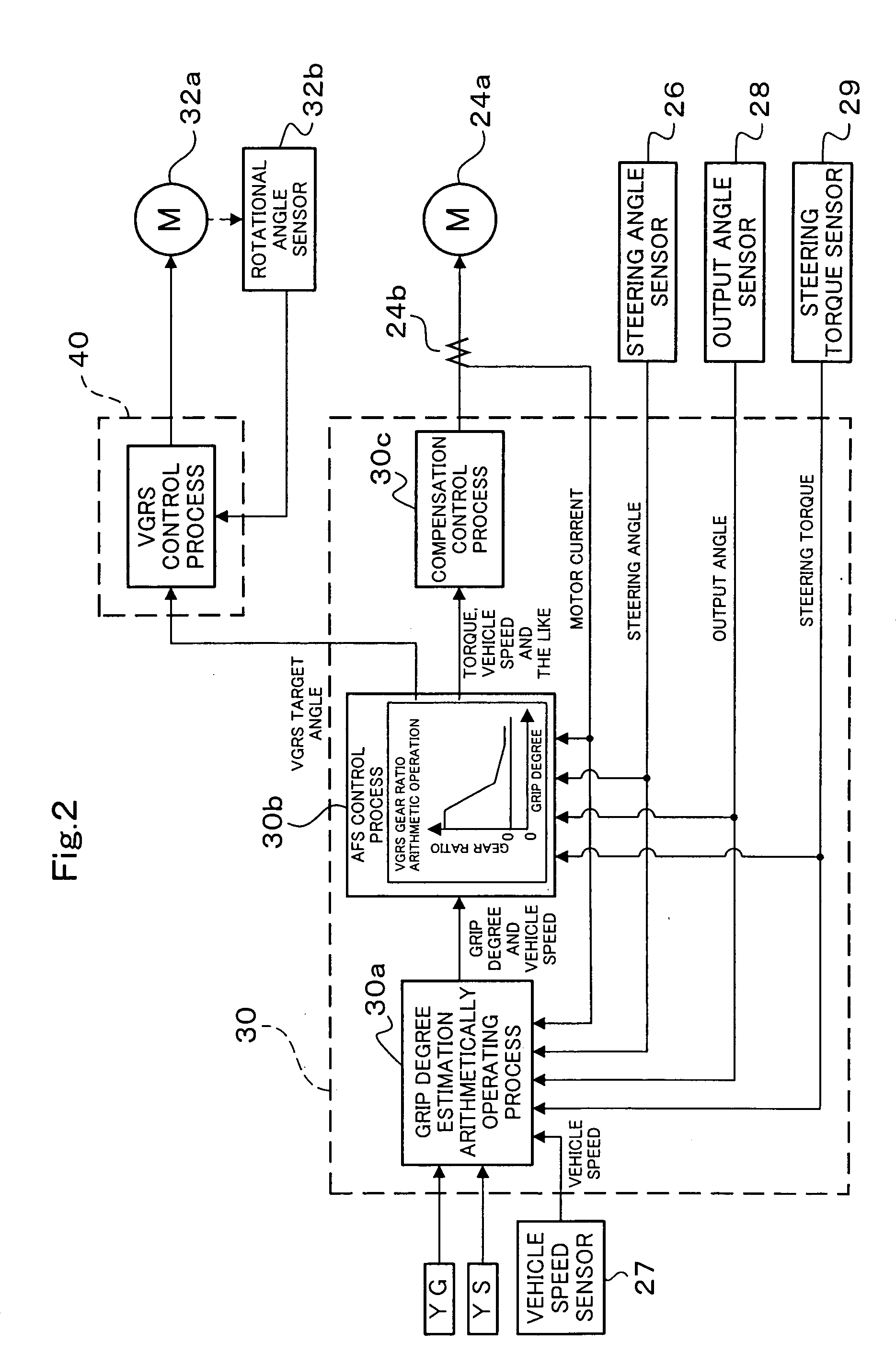
[0018] In accordance with a first aspect of the present invention, a steering force index detecting means detects at least one steering force index of steering indexes including a steering torque and a steering force applied to a steering system from a steering wheel of a vehicle to a suspension, and a self-aligning torque estimating means estimates a self-aligning torque generated in a wheel in a front side of the vehicle on the basis of the detected signal of the steering force index detecting means. Further, a front wheel index estimating means estimates at least one of front wheel indexes including a side force applied to the wheel in the front side of the vehicle and a front wheel slip angle, by using a state quantity of the vehicle detected by a vehicle state quantity detecting means. Further, a grip degree estimating means estimates a grip degree applied to at least the wheel in the front side of the vehicle, on the basis of a change in the self-aligning torque estimated by the self-aligning torque estimating means with respect to the front wheel index estimated by the front Reel index estimating means. A transfer ratio of a transfer ratio variable means is set by a transfer ratio setting means on the basis of the grip degree estimated by the grip degree estimating means. Accordingly, since it is possible to estimate the grip degree which is changed in correspondence to a magnitude of the road surface μ, for example, the grip degree estimated by the grip degree estimating means is reduced in the case that the vehicle runs on the road surface having a low μ, it is possible to set the transfer ratio of the transfer ratio variable means large even at a time when the vehicle runs at the low speed. Therefore, since it is possible to prevent a phenomenon that the steered wheel is largely controlled by a smaller steering angle from being generated in the case that the vehicle runs on the road surface having the low μ, there is obtained an effect that a stability in the vehicle motion can be improved.
[0020] In accordance with a second aspect of the present invention, the transfer ratio setting means sets the transfer ratio such that the transfer ratio is increased in the case that the grip degree gets close to a grip limit of the steered wheel. Accordingly, in the case that the steered wheel gets close to the grip limit, it is possible to increase the transfer ratio and set large even at a time when the vehicle runs at a low speed. Therefore, since it is possible to prevent a phenomenon that the steered wheel is largely controlled by a smaller steering angle from being generated in the case that the vehicle runs on the road surface having the low μ, there is obtained an effect that a stability in the vehicle motion can be improved.
[0023] In accordance with a third aspect of the present invention, the transfer ratio setting means sets the transfer ratio such that the transfer ratio is increased on the basis of a steering speed detected by a steering speed detecting means in the case that the grip degree gets close to a grip limit of the steered wheel. Accordingly, since it is possible to set the transfer ratio, for example, such that the transfer ratio is further increased in correspondence to the increase of the steering speed, in the case of a rapid steering, it is possible to set the larger transfer ratio which is increased further in comparison with the case that the steering wheel is not rapidly steered. Therefore, since it is possible to prevent a phenomenon that the steered wheel is largely controlled from being generated even in the case of the rapid steering such that the vehicle runs on the road surface having the low μ, there is obtained an effect that a stability in the vehicle motion can be improved.
[0026] In accordance with a fourth aspect of the present invention, the transfer ratio setting means sets the transfer ratio such that the transfer ratio is increased on the basis of a vehicle speed detected by a vehicle speed detecting means in the case that the grip degree gets close to a grip limit of the steered wheel. Accordingly, since it is possible to set the transfer ratio, for example, such that the transfer ratio is further increased in correspondence to the increase of the vehicle speed, in the case of a high speed running, it is possible to set the larger transfer ratio which is increased further in comparison with the case that the vehicle does not run at a high speed (for example, the case that the vehicle runs at a middle or low speed or stops). Therefore, since it is possible to prevent a phenomenon that the steered wheel is largely controlled from being generated even in the case that the vehicle runs on the road surface having the low μ at a high speed, there is obtained an effect that a stability in the vehicle motion can be improved.
[0032] In accordance with a fifth aspect of the present invention, the transfer ratio setting means sets the transfer ratio such that the transfer ratio is increased in the case that the grip degree gets close to a grip limit of the steered wheel, and the transfer ratio setting means sets the transfer ratio such that the transfer ratio is reduced in the case that an oversteer state determining means determines that a vehicle state is an oversteer state, and a steer-back rotation detecting means detects that a rotation of the steering wheel is in a steering back direction. Accordingly, since it is possible to set the transfer ratio such that the transfer ratio is reduced in the case that the oversteer state determining means determines that the vehicle state is in the oversteer state, and the steer-back rotation detecting means determines that the rotation of the steering wheel is in the steering back direction, that is, the driver executes a counter steering operation, the driver can easily executed the counter steering operation. Therefore, there is obtained an effect that a stability in the vehicle motion can be improved.
[0036] In accordance with a sixth aspect of the present invention, an understeer / oversteer determining means determines whether the vehicle is in an understeer or an oversteer, and a transfer ratio determining means determines the transfer ratio of the transfer ratio variable means on the basis of a determined result of the understeer / oversteer determining means and the grip degree estimated by the grip degree estimating means. Therefore, since it is possible to change a response of the steering operation in correspondence to the state of the vehicle and the grip state, there is obtained an effect that a stability in the vehicle motion can be improved.

Problems solved by technology

Accordingly, since the steered wheel can be controlled largely by the smaller steering angle even in the case that the vehicle runs on a road in which a frictional coefficient μ of a road surface contacted with the steered wheel (hereinafter, refer to as “road surface μ”) is small, that is, a low μ road surface, there is a problem that a stability in the vehicle motion may be deteriorated.
In other words, since an actual steering angle to a target actual steering angle is controlled with respect to the steering operation, in spite that the steering wheel is kept at a fixed angle by the driver, there is generated a problem that the stability in the vehicle motion may be deteriorated.
Further, the problem that the stability in the vehicle motion is deteriorated may be generated in “a steering apparatus provided with an operating state detecting means for detecting an operating state of a steering wheel so as to output an operating signal, a vehicle speed detecting means for detecting a vehicle speed so as to output a vehicle speed signal, a steering angle determining means for determining a target actual steering angle of a steered wheel on the basis of the operating signal detected by the operating state detecting means and the vehicle speed signal detected by the vehicle speed detecting means, and a steered wheel control means for controlling the steered wheel to the target actual steering angle determined by the steering angle determining means”, that is, a so-called steer-by-wire steering apparatus in which the steering wheel and the steered wheel are mechanically separated.

Method used


Image

  • Steering device
  • Steering device
  • Steering device

Examples


first embodiment

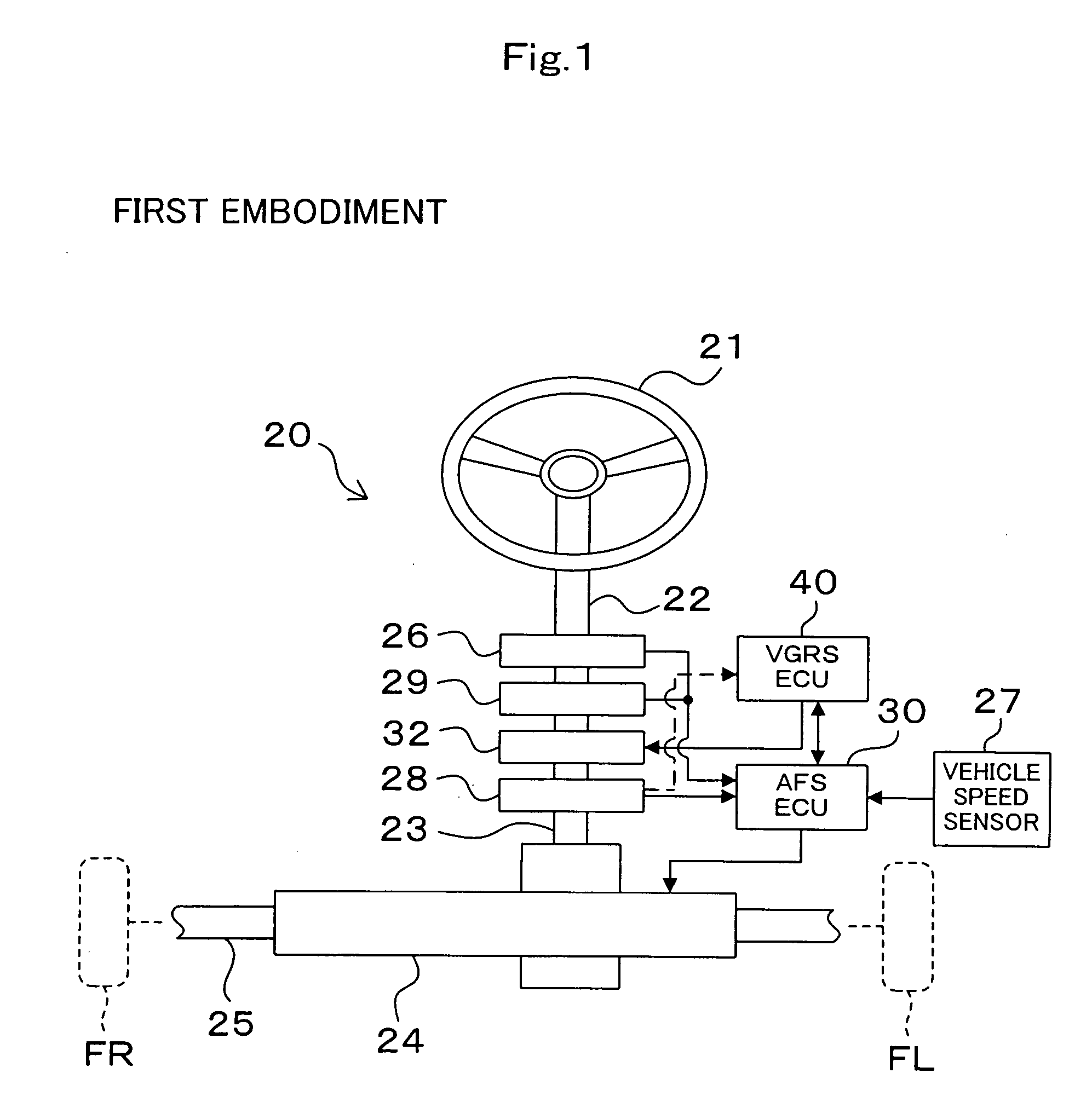
[0083] First, a description will be given of a main structure of a steering apparatus 20 of a first embodiment on the basis of FIG. 1. In this case, the steering apparatus 20 of the first embodiment may correspond to a steering apparatus stated in claim 1 or 2.

[0084] As shown in FIG. 1, the steering apparatus 20 has approximately the same structure as that of the steering apparatus 100 in accordance with the VGRS control shown in FIG. 32. In this case, since a steering wheel 21, a first steering shaft 22, a second steering shaft 23, a rod 25, a steering angle sensor 26, a vehicle speed sensor 27, an output angle sensor 28, a gear ratio variable unit 32 and a VGRS_ECU 40 shown in FIG. 1 respectively may correspond to the steering wheel 111, the first steering shaft 112, the second steering shaft 113, the rod 115, the steering angle sensor 116, the vehicle speed sensor 117, the output angle sensor 118, the gear ratio variable unit 122 and the VGRS_ECU 120 shown in FIG. 32, and are st...

second embodiment

[0135] Next, a description will be given of a steering apparatus of a second embodiment on the basis of FIGS. 15 and 16. In this case, the steering apparatus of the second embodiment may correspond to a steering apparatus stated in claim 1 or 3.

[0136] The steering apparatus of the second embodiment is different from the steering apparatus of the first embodiment in a point that a steering speed vs gear ratio map 30d is added to the grip degree vs gear ratio map 30b in the AFS control process executed by the AFS_ECU 30 of the steering apparatus 20 of the first embodiment mentioned above. Accordingly, since the other constituting parts are substantially the same as the structures of the steering apparatus 20 of the first embodiment, the description thereof will be omitted, and a description will be given with reference to FIGS. 1 and 2 as occasion demands.

[0137] As shown in FIG. 15, in the steering apparatus of the second embodiment, the VGRS target angle is calculated by multiplyin...

third embodiment

[0140] Next, a description will be given of a steering apparatus of a third embodiment on the basis of FIGS. 17 and 18. In this case, the steering apparatus of the third embodiment may correspond to a steering apparatus stated in claim 1 or 4.

[0141] The steering apparatus of the third embodiment is different from the steering apparatus of the first embodiment in a point that a vehicle speed vs gear ratio gain map 30e is added to the grip degree vs gear ratio map 30b in the AFS control process executed by the AFS_ECU 30 of the steering apparatus 20 of the first embodiment mentioned above. Accordingly, since the other constituting parts are substantially the same as the structures of the steering apparatus 20 of the first embodiment, the description thereof will be emitted, and a description will be given with reference to FIGS. 1 and 2 as occasion demands. In this case, the vehicle speed is arithmetically operated by the AFS_ECU 30 on the basis of the vehicle speed signal detected a...


PUM


Abstract

In accordance with a steering apparatus (20), a grip state between a ground surface on which a steered wheel is grounded and the steered wheel is estimated by a grip degree estimation arithmetically operating process (30a) which is arithmetically operated by AFS_ECU (30), and VGRS target angle is set such that a steering gear ratio is increased in the case that the grip degree gets close to a grip limit on the basis of an estimated grip state, in accordance with a grip degree vs gear ratio map (30b). Accordingly, since it is possible to estimate the grip degree which is changed in correspondence to a magnitude of the road surface it, for example, in the case that the steered wheel gets close to the grip limit, it is possible to increase the steering gear ratio so as to set large even at a time when the vehicle runs at the low speed. Therefore, since it is possible to prevent a phenomenon that the steered wheel is largely controlled by a smaller steering angle from being generated in the case that the vehicle runs on the road surface having the low μ, there is obtained an effect that a stability in the vehicle motion can be improved.

Description

CROSS-REFERENCE TO RELATED APPLICATION [0001] The present application claims priority under 35 U.S.C. §119 to Japanese Patent Application No. JP 2002-153072. The contents of these applications are incorporated herein by reference. TECHNICAL FIELD [0002] The present invention relates to a steering apparatus provided with a transfer ratio variable means for varying a transfer ratio by driving an electric motor in the middle of a steering transmission system connecting a steering wheel to a steered wheel. BACKGROUND ART [0003] As a structure provided with the transfer ratio variable means for varying the transfer ratio by driving the electric motor in the middle of the steering transmission system connecting the steering wheel to the steered wheel, there is a steering apparatus 100 constituted by a steering wheel 111, a first steering shaft 112, a second steering shaft 113, a steering gear box 114, a steering angle sensor 116, a vehicle speed sensor 117, an output angle sensor 118, VGR...

Claims


Application Information

Patent Timeline
Patent Type & Authority Applications(United States)
IPC IPC(8): B62D5/00B62D5/04B62D6/00B62D101/00B62D113/00B62D119/00B62D137/00
CPCB62D6/006B62D5/008
Inventor KATO, HIROAKIMOMIYAMA, MINEKAZUOGAWA, SHOJIASANO, KENJIIMOTO, YUZOUYASUI, YOSHIYUKITANAKA, WATARUONO, EIICHIMURAGISHI, YUJI
Owner JTEKT CORP
Learn More