Ergonomic fluid dispenser

a fluid dispenser and ergonomic technology, applied in the field of fluid dispensers, can solve the problems of adhesive leakage back across the piston, the type of fluid dispenser has a number of limitations, and the operator's kneeling or bending, so as to facilitate the application of less problems, speed up the application time, and eliminate kneeling or bending.

Inactive Publication Date: 2005-10-06
ILLINOIS TOOL WORKS INC
View PDF49 Cites 13 Cited by
  • Summary
  • Abstract
  • Description
  • Claims
  • Application Information

AI Technical Summary

Benefits of technology

[0012] The present invention meets this need by providing an ergonomic fluid dispenser. The ergonomic fluid dispenser may include a fluid container, a dispensing assembly, an input energy / drive system, and a carrying case for carrying the components. The ergonomic focus is to provide an advantageous position for operating the fluid dispenser, facilitating fewer problems for the operator during application. This includes, but is not limited to, keeping the operator upright, eliminating kneeling or bending, which can also speed up application time, and reducing the torque on the wrist, arm and shoulder caused by the weight of the fluid in the dispensing assembly. The present invention also allows optimization of the size of the fluid container to minimize downtime for adhesive refills.

Problems solved by technology

However, this type of fluid dispenser has a number of limitations.
The use of the external push rod to move the piston plate causes column compression loading, which can buckle the cartridge if the friction resistance or back pressure becomes excessive.
Since the fit between the piston and cartridge must be tight without clearance in order to operate properly, any ballooning will cause the adhesive to leak back across the piston.
The bleed back of adhesive causes malfunctioning of the cartridge and contaminates the push rod of the dispenser.
The tight fit between the piston and the cartridge tube also increases the piston friction, which requires more work to operate the push rod.
The tight fit can also cause quality problems in manufacturing.
Moreover, because the operation of the cartridge depends on a dispenser with its associated hardware, the system is prone to damage as a result of improper handling during use or refilling.
Furthermore, the small nozzle is short.
These positions are not good ergonomically, and can lead to accumulated trauma disorders.
However, it is also subject to damage during use, and the operator must stop frequently to replace the adhesive cartridge.
Although the extended hand gun improves the application posture, it is worse with respect to the ergonomics of the wrist, arm, and shoulder because of the increased torque that occurs when the 4 lbs. of gun and cartridge are on the opposite end of the extension for the hand gun.
The handgrip pull force is ergonomically challenging because the small nozzle causes backpressure force during dispensing.
The manual operation of the hand gun can lead to carpal tunnel syndrome over time.
Operators sometimes cut the nozzle off to decrease the backpressure, but the resulting increased flow rate requires the operator to apply the adhesive with a sweeping arm motion, which results in sloppy and variable application.
The application of adhesive is generally the limiting factor in the operation, because it takes a long time to apply the adhesive properly, especially with the fatigue that occurs from the poor ergonomic posture.
High viscosity adhesives could not be used in these systems because their piston or gear pumps require gravity free flow into the intake, and these adhesives would cause cavitations.
The use of a high viscosity adhesive would destroy the hose and tubes if it hardened in them.

Method used


Image

  • Ergonomic fluid dispenser
  • Ergonomic fluid dispenser
  • Ergonomic fluid dispenser

Examples


Embodiment Construction

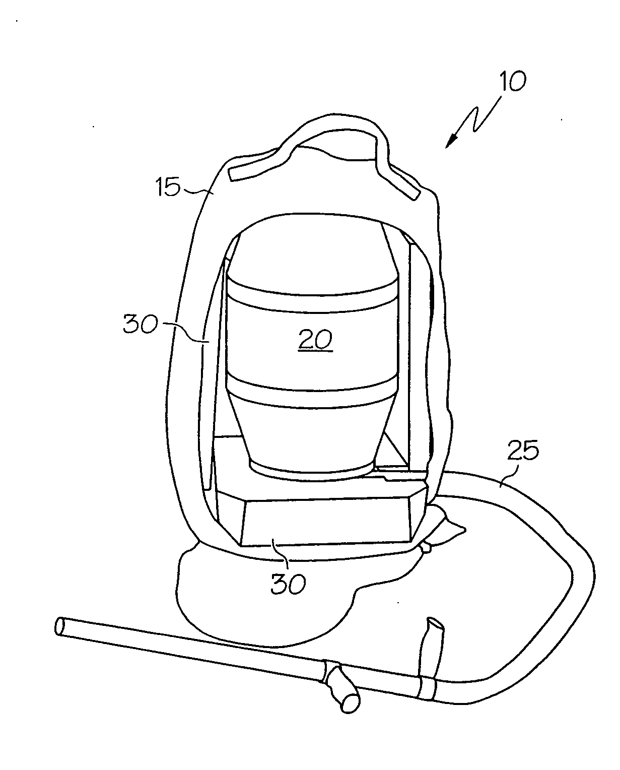
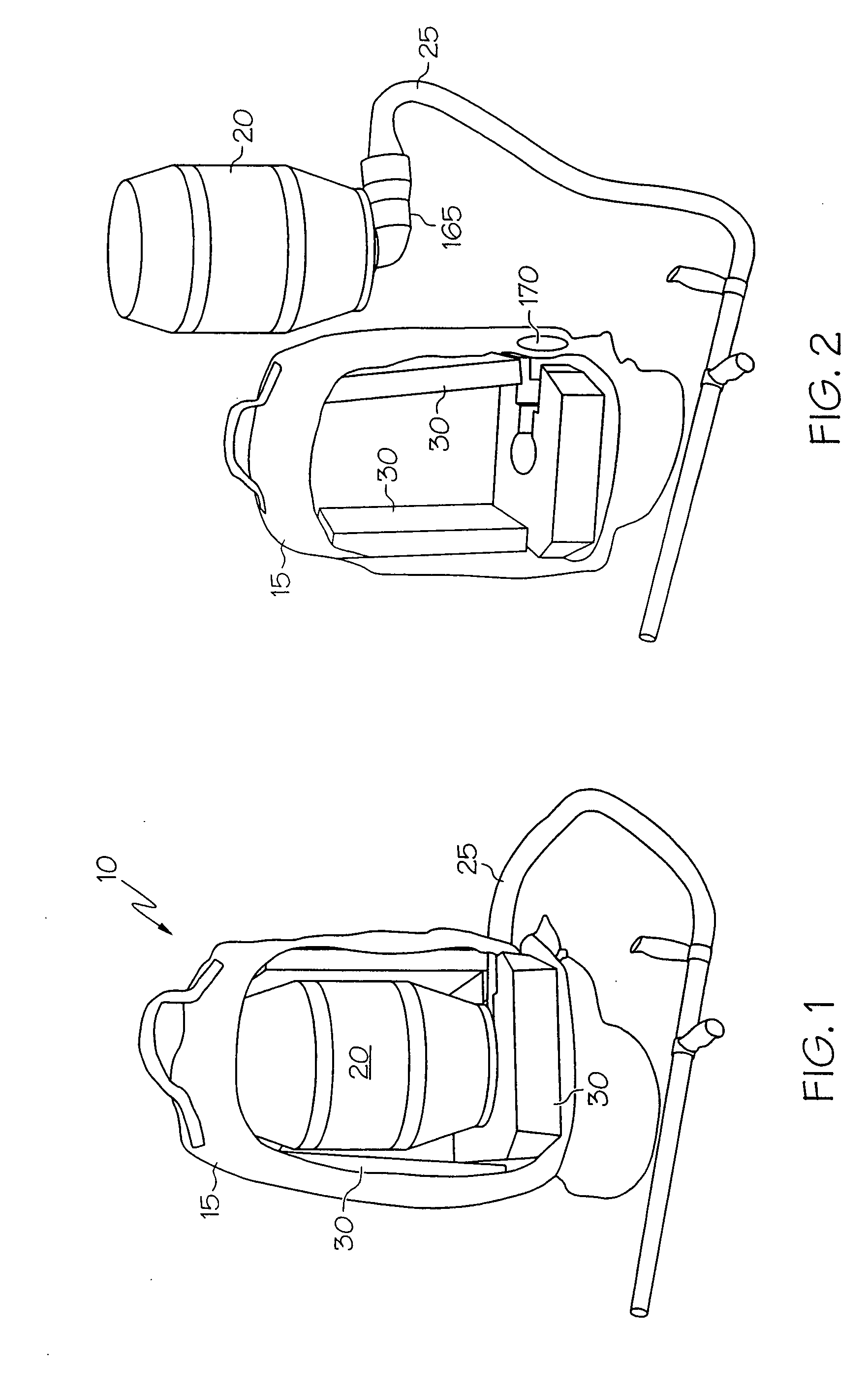
[0050] The ergonomic fluid dispenser of the present invention includes a fluid container, a dispensing assembly, an input energy / drive system, and a carrying case for carrying the components.

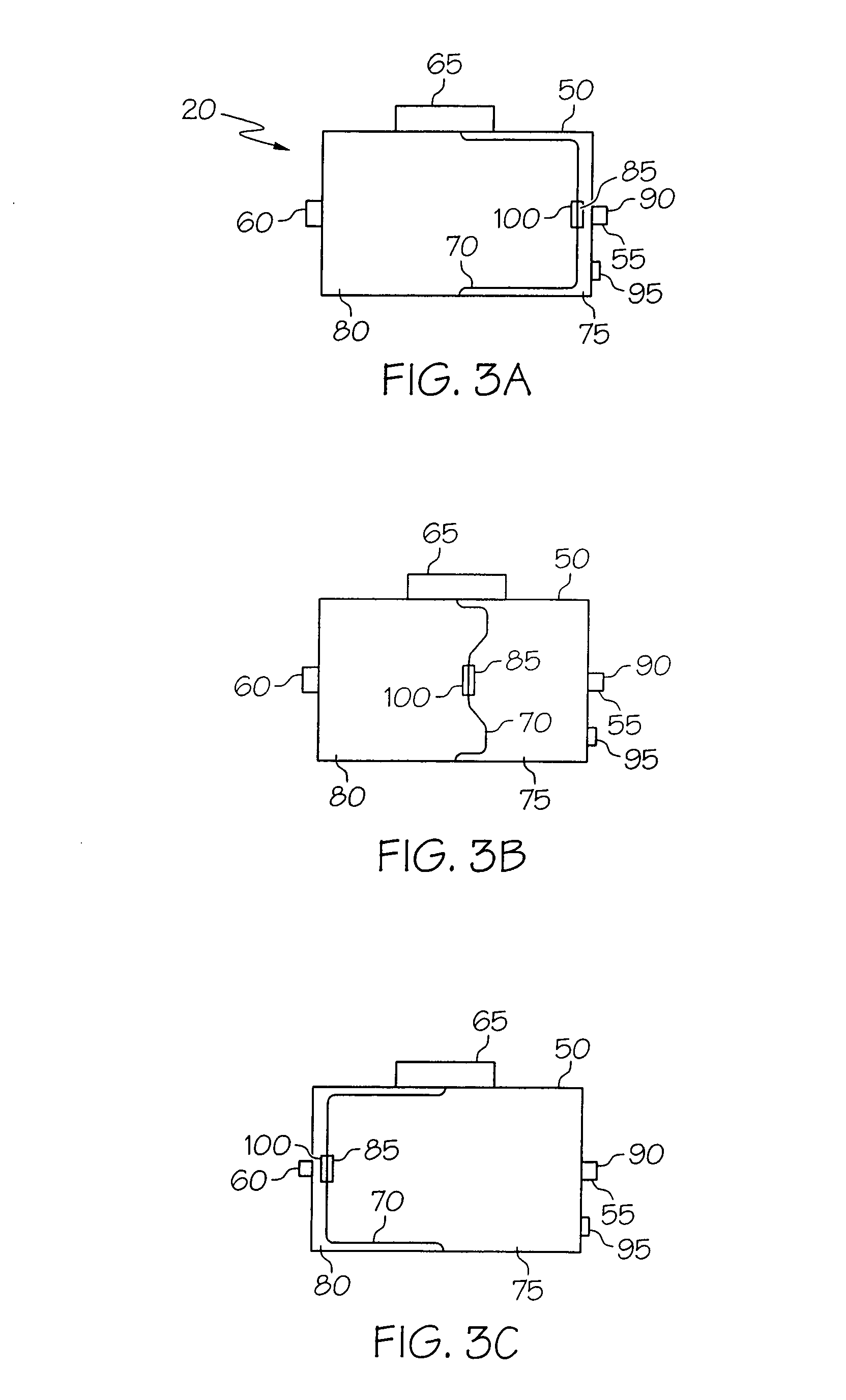
[0051] The fluid container can utilize a two chamber concept, if desired. In one embodiment of this type of arrangement, there is a divider inside a bottle which separates the bottle into two chambers: an air chamber and a fluid chamber. The divider acts as a piston. When air is delivered to the air chamber side of the bottle, the air pressure pushes on the divider so that it applies a force against the adhesive on the other side of it. The applied force results in the adhesive being pushed out of the fluid container.

[0052] A dispensing assembly is connected to the fluid container. The diameter and length dimensions of the dispensing assembly are chosen so that a high viscosity adhesive can be dispensed at low pressure at a desired flow rate. The low pressure condition allows all of the compon...


PUM


Abstract

An ergonomic fluid dispenser. The ergonomic fluid dispenser includes a fluid container, a dispensing assembly, and a carrying case. The ergonomic fluid dispenser allows a user to remain standing during application of the fluid.

Description

[0001] The present application claims priority to U.S. Provisional Application Ser. No. 60 / 558,188, filed Mar. 31, 2004, entitled “Ergonomic Fluid Dispenser,” and U.S. Provisional Application Ser. No. 60 / 586,007, filed Jul. 7, 2004, entitled “Ergonomic Fluid Dispenser.”BACKGROUND OF THE INVENTION [0002] The present invention relates generally to a fluid dispenser, and more particularly to an ergonomically designed fluid dispenser that allows a user to remain standing during application. [0003] Applying adhesive during construction to sub-floors, drywall, and other surfaces typically involves the use of a manual or pneumatic hand gun with a disposable adhesive cartridge. The disposable adhesive cartridges are usually made from spiral wound paper cores which may be reinforced circumferentially with metallized film, to help make them hermetic. The cartridges are sometimes made of plastic tube. There is a piston plate on the drive end of the cartridge, and a small nozzle on the other en...

Claims


Application Information

Patent Timeline
Patent Type & Authority Applications(United States)
IPC IPC(8): B05B9/08B67D7/84
CPCB05B9/08B05B9/0888B05B9/0805
Inventor MCMAHON, MICHAEL J.PIOTROWSKI, STANLEYDOEHLER, STEVEDINCOLO, MICHAELJAMES, JAMES V.
Owner ILLINOIS TOOL WORKS INC
Why Eureka
Try Eureka