Plasma display panel and plasma display

a plasma display panel and display panel technology, applied in static indicating devices, instruments, gas-filled discharge tubes, etc., can solve the problems of affecting the display quality, affecting the discharge state, so as to improve the discharge state

Inactive Publication Date: 2005-10-06
PANASONIC CORP
View PDF6 Cites 9 Cited by
  • Summary
  • Abstract
  • Description
  • Claims
  • Application Information

AI Technical Summary

Benefits of technology

[0027] In view of the above demands, the present invention aims to provide a plasma display panel and a plasma display device in which the state of discharger is improved.

Problems solved by technology

This cross talk is the cause of anomalous emission of light, which worsens the display quality.
Therefore, the whole region of the shadow mask inevitably has the same electric potential.
As a result, in the case of performing the address discharge in the normal way for the AC type PDP between the address electrode and one of the display electrodes, an electric field which is generated by the metal shadow mask impedes a charge transfer to the surface of the display electrode in the cell which is to be addressed, and the address discharge becomes difficult.
However, the cross talk infrequently occurs in the conventional PDPS by a charge transfer through narrow gaps provided as gas flow paths.

Method used


Image

  • Plasma display panel and plasma display
  • Plasma display panel and plasma display
  • Plasma display panel and plasma display

Examples


first embodiment

The first embodiment

1. The overall configuration of the PDP device 1000

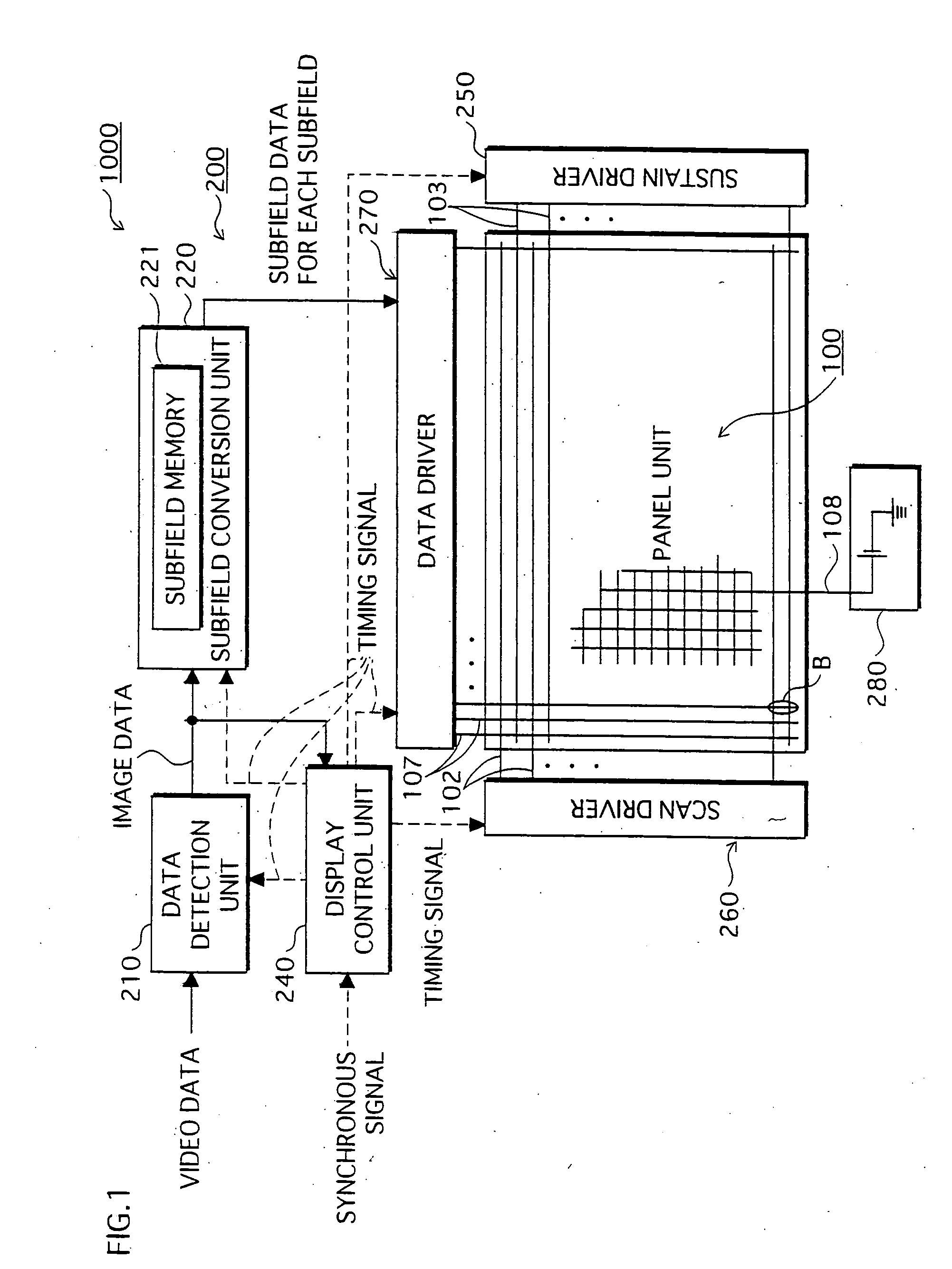
[0073]FIG. 1 is a block diagram which shows the overall configuration of the AC type PDP device according to the present invention.

[0074] As FIG. 1 shows, The PDP device 1000 includes a panel unit 100 for displaying images, and a display driving unit 200 for driving the panel unit 100 based on the intra-field time division gradation display technique.

1-1. The Structure of the Panel Unit 100

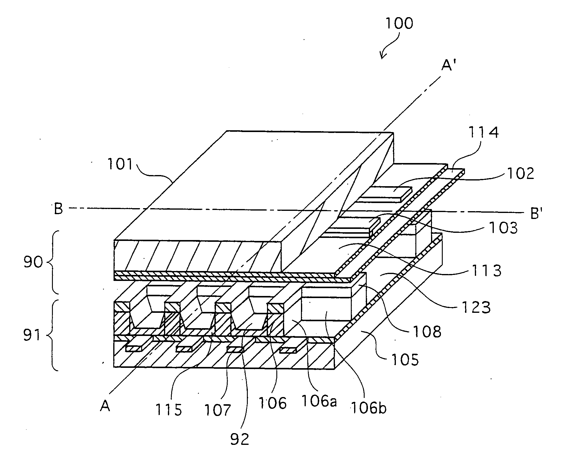
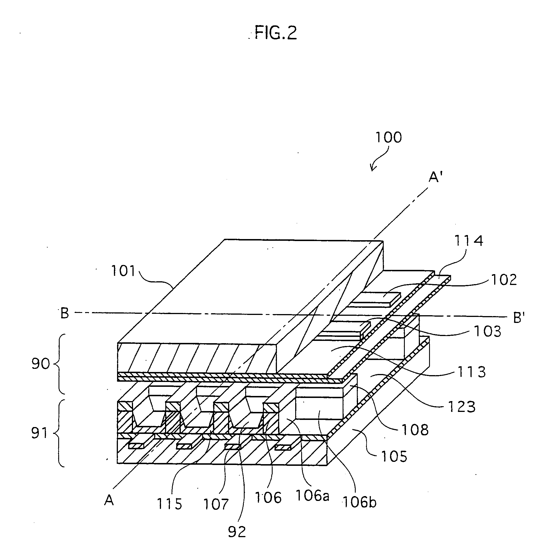
[0075] The following is the description of the structure of the panel unit 100 with reference to FIG. 2, FIG. 3A and FIG. 3B.

[0076]FIG. 2 is a perspective view which typically shows the configuration of the panel unit 100. FIG. 3A is a cross-sectional view of the panel unit 100 taken along the line B-B′, and FIG. 3B is a cross-sectional view of the panel unit 100 taken along the line A-A′.

[0077] As FIG. 1 shows, the panel unit 100 comprises the front plate 90 and the back plate 91 which are disposed so as to face each oth...

second embodiment

The Second Embodiment

2-1. The Structure of the Panel Unit 500 The following is a description of the panel unit 500 according to the second embodiment.

[0120] The difference between the above-described panel unit 100 according to the first embodiment and the panel unit 500 is only in the configuration of the back plate. The panel unit 500 is driven by the display driving unit 200 just as the PDP device 1000.

[0121] More specifically, in the panel unit 500, the guide electrode is disposed at a different position from that of the panel unit 100.

[0122] The following is a detailed description of the difference between the panel unit 500 and the panel unit 100, with reference to FIG. 4, FIG. 5A, and FIG. 5B.

[0123]FIG. 4 is a perspective view which typically shows the configuration of the panel unit 500. FIG. 5A is a cross-sectional view of the panel unit 500 taken along the line D-D′, and FIG. 5B is a cross-sectional view of the panel unit 500 taken along the line C-C′.

[0124] Note tha...

third embodiment

The Third Embodiment

3-1. The Structure of the PDP Device 1500

[0140] The following is a description of the AC type PDP device 1500 according to the third embodiment.

[0141] As FIG. 6 shows, the PDP device 1500 includes a panel unit 100 for displaying images, and a display driving unit 201 for driving the panel unit 100 based on the intra-field time division gradation display technique.

[0142] The display driving unit 201 is different from the display driving unit 200 of the first and second embodiment only in the manner of applying voltage to the guide electrode.

3-2. The Configuration of the Display Driving Unit 201

[0143] The following is a detailed description of the display driving unit 201.

[0144] Comparing the display driving unit 201 with the display driving unit 200, a display control unit 239, instead of the display control unit 240, is disposed in the display driving unit 201 as FIG. 6 shows.

[0145] Also, a pulse generator 275 is added between a guide electrode control uni...


PUM


Abstract

A plasma display panel in which a plurality of pairs of first and second electrodes are disposed on a first substrate so as to be parallel to each other, a plurality of third electrodes are disposed on a second substrate, and main parts of a plurality of barrier ribs are disposed between adjacent third electrodes, the third electrodes being orthogonal to a longitudinal direction of display electrodes each of which consists of a pair of the first and second electrodes, wherein a plurality of fourth electrodes are fixed to the barrier ribs or areas of a surface of the first substrate facing the barrier ribs so as to be at least in vicinities of areas between adjacent display electrodes, the fourth electrodes being electrically exposed to discharge spaces which are defined by the barrier ribs.

Description

TECHNICAL FIELD [0001] The present invention relates to a plasma display panel and a plasma display device used as a display device and the like, and more specifically relates to a technique for improving a state of a discharge. BACKGROUND ART [0002] In recent years, among display devices used for computers and televisions, plasma display panels (hereinafter called “PDPs”) are drawing attentions as display devices that can have large screens but can be thin and lightweight. [0003] The PDPs are display devices which realize a color display by irradiating phosphors (of red, green and blue) with ultraviolet rays, which is generated when a discharge of plasma is caused in a gas, so as to obtain visible light. [0004] When the above discharge of plasma is caused, an anomalous discharge between adjacent cells, which is a so-called cross talk, can occur. This cross talk is the cause of anomalous emission of light, which worsens the display quality. [0005] To solve this problem, one of conve...

Claims


Application Information

Patent Timeline
Patent Type & Authority Applications(United States)
IPC IPC(8): G09G3/293G09G3/294G09G3/298H01J17/49
CPCG09G3/293G09G3/294G09G3/2986H01J11/36H01J11/12H01J11/28G09G2320/0209H01J11/32
Inventor KITAGAWA, MASATOSHITERAUCHI, MASAHARUMORTA, YUKIHIROHASHIMOTO, SHINICHIRO
Owner PANASONIC CORP
Why Eureka
Try Eureka