Apparatus and process for detecting condensation in a heat exchanger

a technology of heat exchanger and process, applied in the field of heat exchangers, can solve the problems of high corrosiveness and water condensing on the tub

Inactive Publication Date: 2005-10-06
NOOTER ERIKSEN INC
View PDF5 Cites 5 Cited by
  • Summary
  • Abstract
  • Description
  • Claims
  • Application Information

AI Technical Summary

Problems solved by technology

However, the low temperature feedwater has the capacity to bring the tubes at the downstream end of the feedwater heater below the dew point of the water in the exhaust gases, and when this occurs, water condenses on tubes.
The oxides of sulfur in the flue gas unite with that water to form sulfuric acid which is highly corrosive.
And to be safe, the temperature of the entering water needs to be high, because the dew point temperature of the gases is difficult to predict in that it is a function of several parameters.

Method used


Image

  • Apparatus and process for detecting condensation in a heat exchanger
  • Apparatus and process for detecting condensation in a heat exchanger

Examples


Embodiment Construction

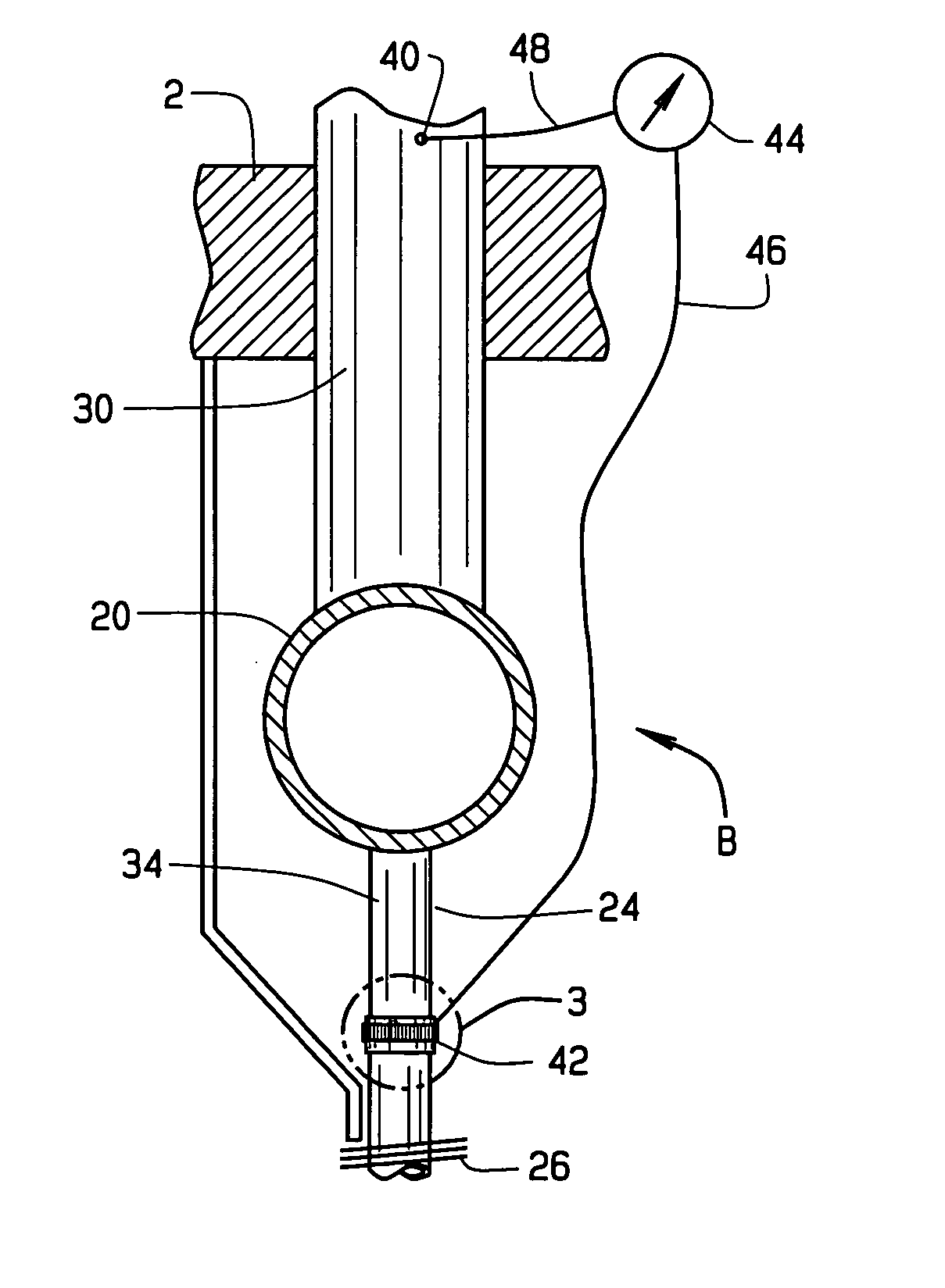
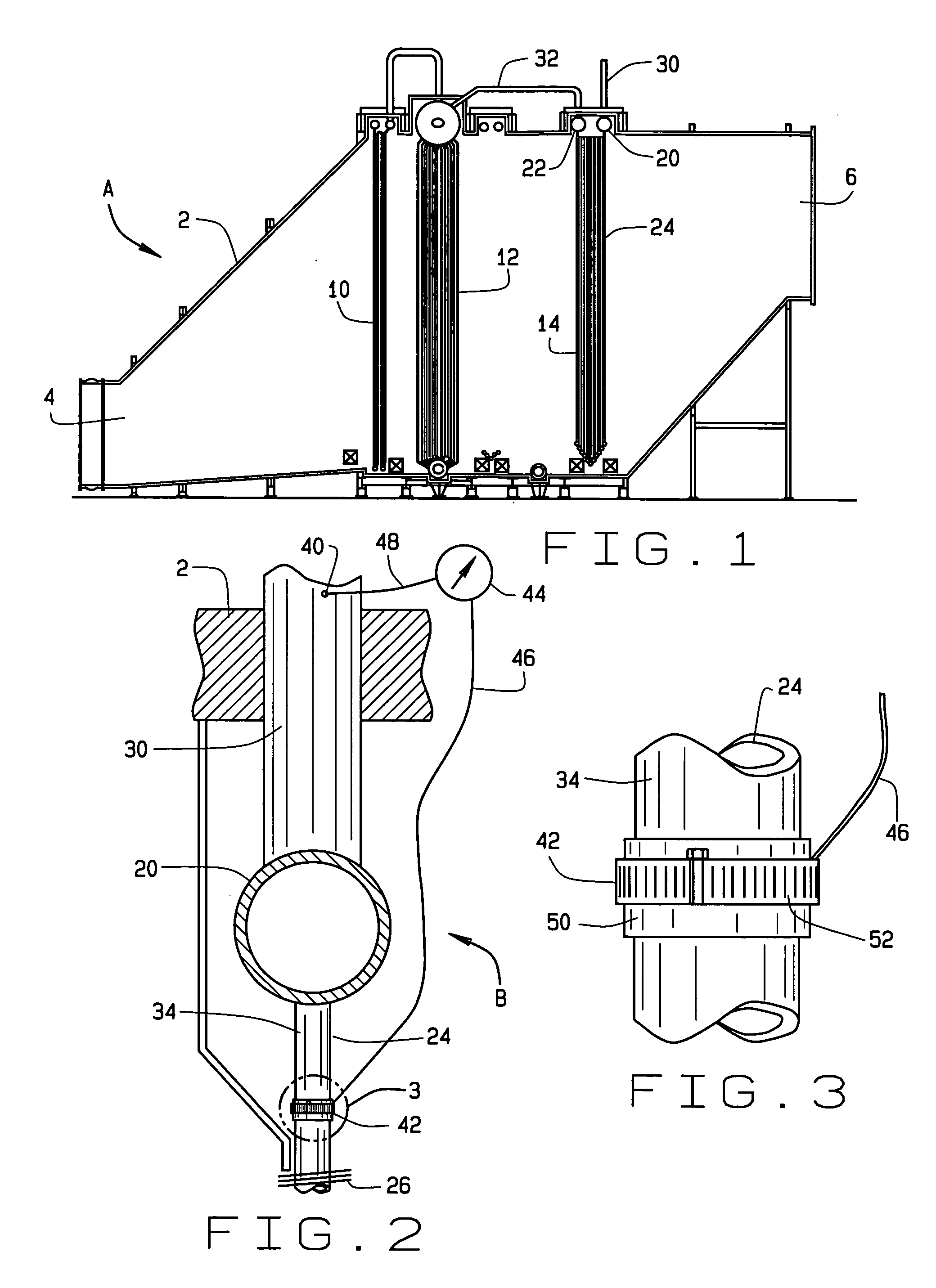
[0012] Referring now to the drawings a heat recovery steam generator (HRSG) A (FIG. 1) contains a dew point monitoring unit B (FIG. 2) which provides HRSG with a system that detects the presence of condensation in the. HRSG A and produces and alarm or other signal. This enables the operator of the HRSG to control the temperature of water entering the HRSG so that surfaces within the HRSG remain above the temperature at which condensate will form on them, yet not excessively above that temperature.

[0013] The HRSG A includes a duct 2 having an inlet end 4 and a discharge end 6 which leads into a stack or flue. Hot gases derived from the combustion of natural gas or some other fuel enter the duct 2 at the inlet end 4, pass through it, and leave at the discharge end 6. The gases contain carbon dioxide and steam and trace mounts of compounds which if united with liquid water can form corrosive substances such as acids.

[0014] In addition to the duct 2, the HRSG includes several heat exc...


PUM


Abstract

A feedwater heater for an HRSG is provided with a monitoring unit for detecting the presence of condensation in the feedwater heater. The monitoring unit includes a dielectric band around one of the tubes of the feedwater heater near the location where the feedwater is directed into the heater and a conductive band located around the dielectric band. The unit also includes a conductivity sensor installed between a ground on the feedwater heater and the conductive element. Hot gases containing moisture pass through the feedwater heater, and if the temperature of surfaces in the region of the tube around which the dielectric and conductive bands extend drops below the dew point of the gas, an electrically conductive condensate will appear those surfaces and on the tube and will flow over the dielectric band, completing an electric circuit between the tube and the conductive band. The conductivity sensor detects this and hence detects the presence of the condensation.

Description

CROSS-REFERENCE TO RELATED APPLICATIONS [0001] This application derives and claims priority from U.S. provisional application 60 / 557,626 filed Mar. 30, 2004.STATEMENT REGARDING FEDERALLY SPONSORED RESEARCH [0002] Not applicable. BACKGROUND OF THE INVENTION [0003] This invention relates in general to heat exchangers and, more particularly, to a process and apparatus for detecting condensation in a heat exchanger. [0004] Natural gas represents a significant source of electrical-energy in the United States. It burns with few emissions, and is available throughout much of the country. Moreover, the plants which convert it into electrical energy are efficient and, in comparison to hydroelectric projects and coal-fired plants, they are relatively easy and inexpensive to construct. In the typical plant, the natural gas burns in a gas turbine which powers an electrical generator. The exhaust gases—essentially carbon dioxide and steam—leave the gas turbine at about 1200’0 F. (649° C.) and th...

Claims


Application Information

Patent Timeline
Patent Type & Authority Applications(United States)
IPC IPC(8): F02C6/00F02G1/00F02G3/00F22B37/02F24H9/00F28F19/00G01R27/26
CPCF22B37/025F28F19/00F24H9/0036F22B37/02F24H9/00
Inventor SCHROEDER, JOSEPH E.
Owner NOOTER ERIKSEN INC
Why Eureka
Try Eureka