[0021] With this feature, in a state in which the security sensor is fixed to a fixed object surface to which the security sensor is fixed, the elastic switch member elastically deforms by receiving a pushing force from the fixed object surface, and depresses the switch actuating member, while maintaining the
closed state of the above-described tamper opening. Thus, the tamper switch body recognizes that the security sensor is fixed to the fixed object surface, and therefore does not transmit the tampering detection signal (trouble signal). Even if this security sensor is installed outside and rainwater or the like pours over it, rainwater or the like will not enter into the housing of the security sensor, since the tamper opening is maintained in a
closed state by the elastic switch member. Then, the security sensor has been removed from the fixed object surface in an attempt of illegal intrusion or the like, the pushing force received by the elastic switch member from the fixed object surface to which the security sensor is fixed is released, and the elastic switch member is restored in a shape to which no external force is applied, releasing the depressing of the switch actuating member. Thus, the tamper switch body recognizes that the security sensor has been removed from the fixed object surface to which the security sensor has been fixed, and therefore transmits the tampering detection signal (trouble signal). In this way, in this solving means, the elastic switch member that depresses the switch actuating member by elastically deforming by the pushing force from the fixed object surface to which the security sensor is fixed is mounted in the tamper opening of the housing. Accordingly, it is possible to prevent a flood into the security sensor by rain or the like, while providing the security sensor with the tampering detection function, thus making it possible to realize outdoor installation of the security sensor having the tampering detection function.
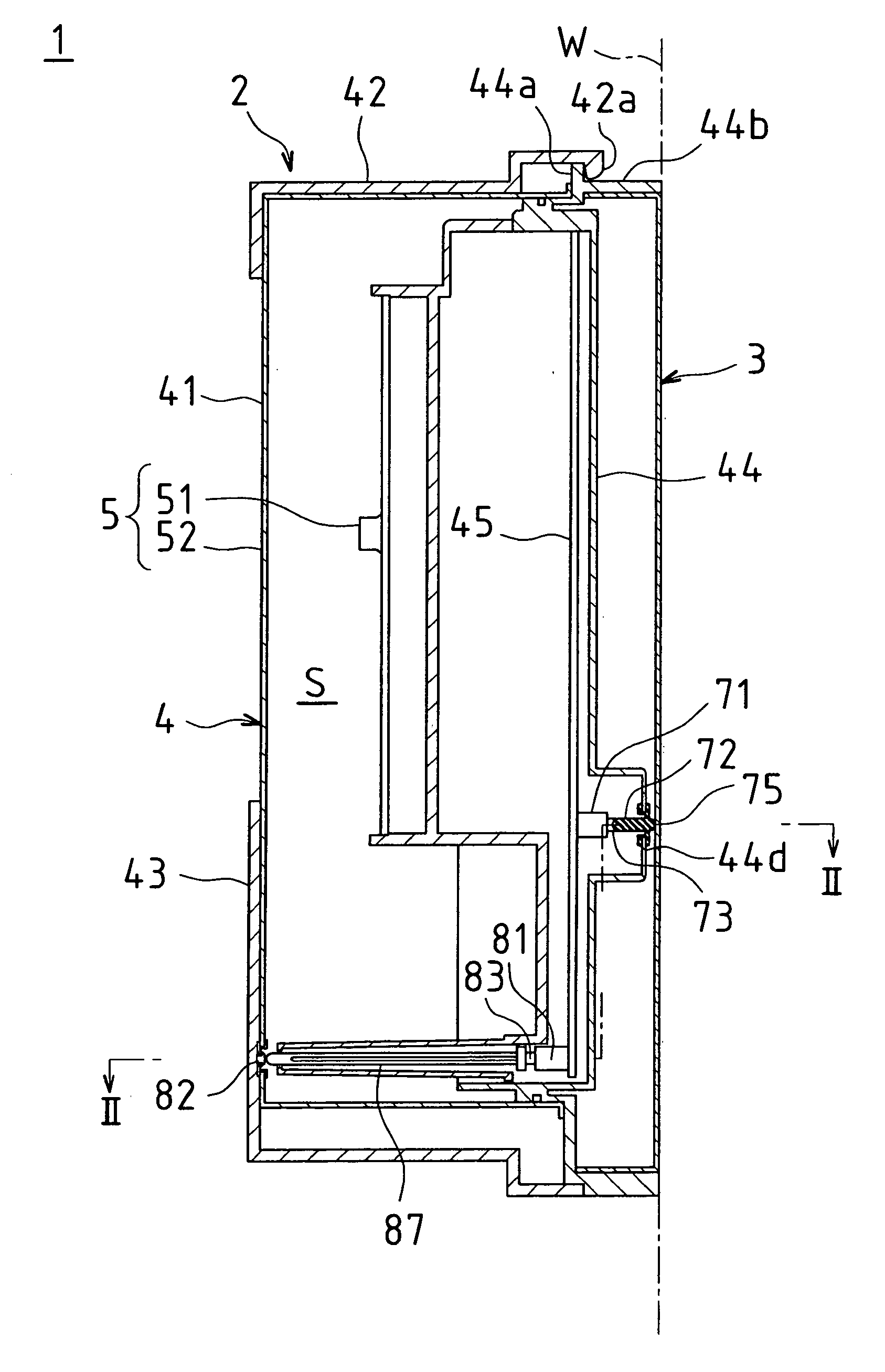
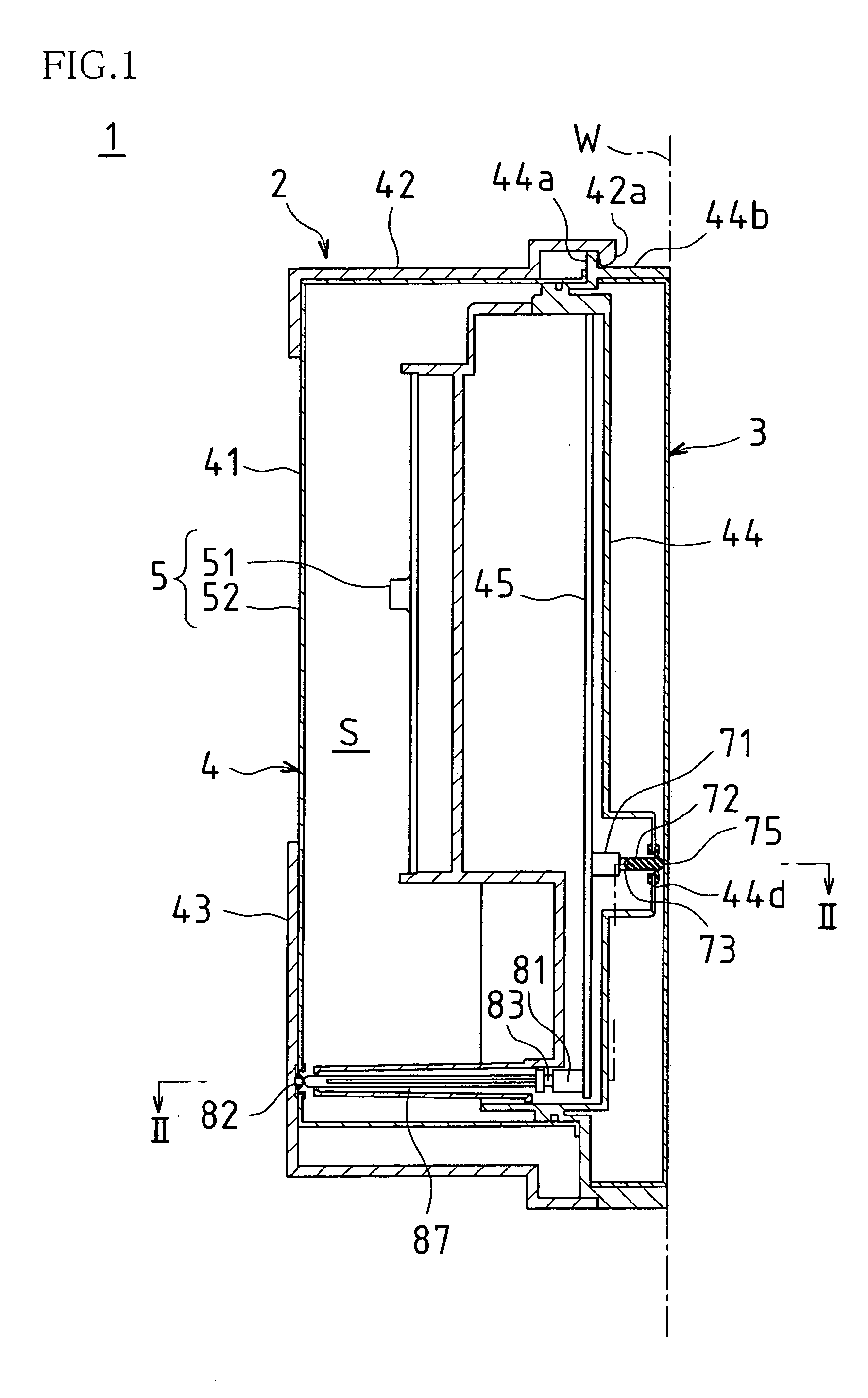
[0022] A specific configuration of the elastic switch member in this case may include a sealing portion, a pressure-receiving projection portion and an actuating projection portion. The sealing portion is a portion that seals the inside of the housing by contacting an inner surface of the tamper opening to close the tamper opening. The pressure-receiving projection portion is a portion that is integrally formed with the sealing portion and that receives a pushing force from the fixed object surface to which the security sensor is fixed in a fixed state. The actuating projection portion is a portion that is integrally formed with the sealing portion and that applies a pushing force in a depressing direction to the switch actuating member of the tamper switch body through elastic deformation of the sealing portion by the pressure-receiving projection portion receiving a pushing force from the fixed object surface to which the security sensor is fixed in a fixed state. That is, in this elastic switch member, the sealing portion elastically deforms, while sealing the inside of the housing by closing the tamper opening, thereby allowing the pushing force received by the pressure-receiving projection portion from the fixed object surface to which the security sensor is fixed to be acted upon the switch actuating member of the tamper switch body via the actuating projection portion. Accordingly, it is possible to perform a highly reliable tampering detection operation.
[0024] In the case of this solving means, in a state in which the second cover is mounted on the first cover, the elastic switch member elastically deforms by receiving a pushing force from the second cover, thereby rendering the switch actuating member in a depressed state, while maintaining the
closed state of the above-described tamper opening. Thus, the tamper switch body recognizes that the second cover is mounted on the first cover, and therefore does not transmit the tampering detection signal (trouble signal). Even if this security sensor is installed outside and water enters the gap between the first cover and the second cover because of rainwater or the like pouring over it, rainwater or the like will not enter into the housing (into the first cover) of the security sensor, since the above-described tamper opening is maintained in a closed state by the elastic switch member. Then, when the second cover has been removed from the first cover in an attempt of illegal intrusion or the like, the pushing force received by the elastic switch member from the second cover is released, and the elastic switch member is restored in a shape to which no external force is applied, releasing the depressing of the switch actuating member. Thus, the tamper switch body recognizes that the second cover has been removed from the first cover, and therefore transmits the tampering detection signal (trouble signal). In this way, also with this solving means, it is possible to prevent a flood into the sensor by rain or the like, while providing the security sensor with the tampering detection function, thus making it possible to realize outdoor installation of the security sensor having the tampering detection function.
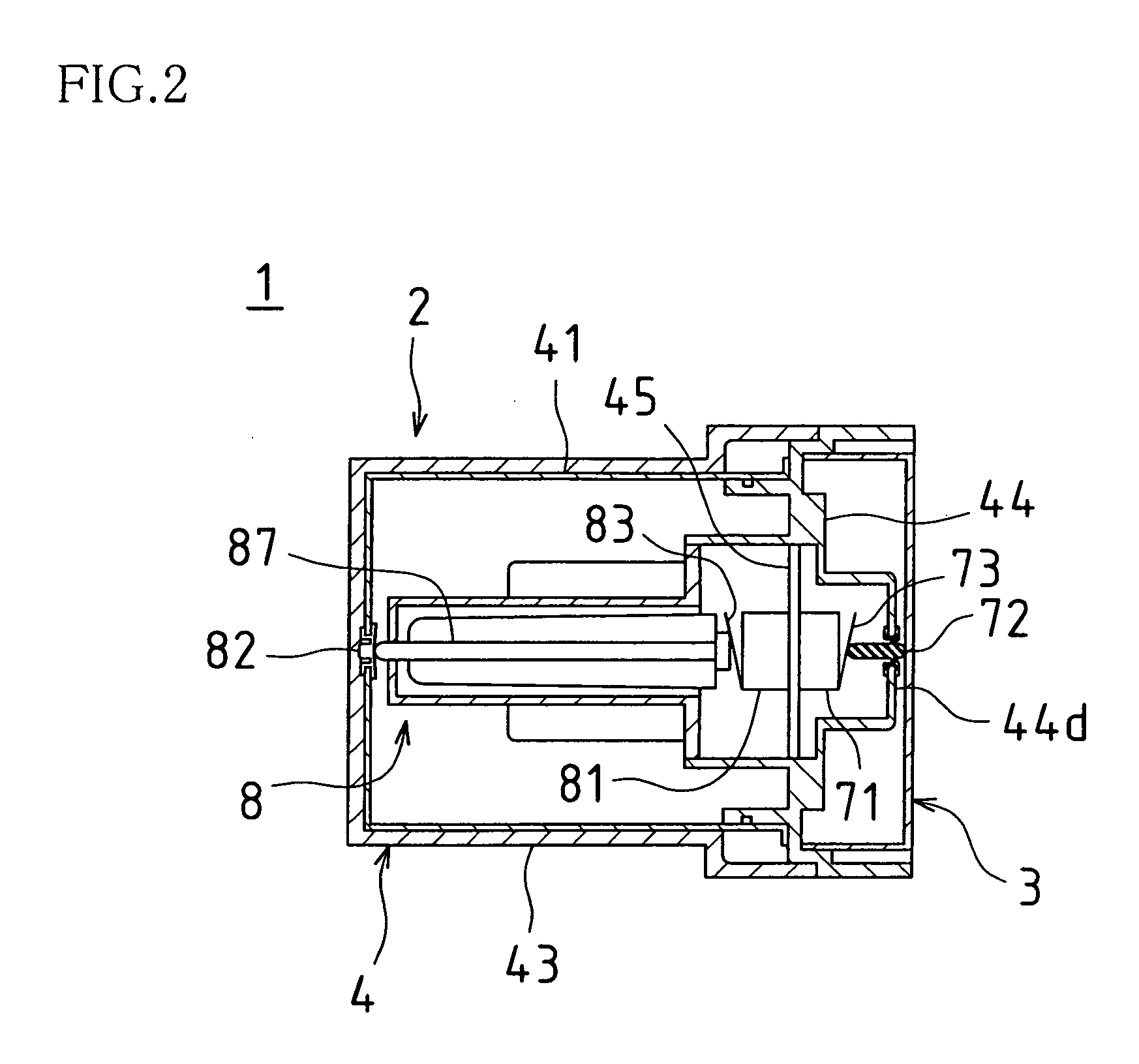
[0025] In a specific configuration of the elastic switch member in this case, the elastic switch member may be connected with the switch actuating member of the tamper switch body via a connection pin, and may include a sealing portion and a pressure-receiving projection portion. The sealing portion is a portion that seals the inside of the housing by contacting an inner surface of the tamper opening to close the tamper opening. The pressure-receiving projection portion is a portion that is integrally formed with the sealing portion and that receives a pushing force from the second cover in a mounted state of the second cover. The back surface of the pressure-receiving projection portion applies an operational force to the connection pin through elastic deformation of the sealing portion by the pressure-receiving projection portion receiving a pushing force from the second cover in a mounted state of the second cover, and the connection pin applies a pushing force in a depressing direction to the switch actuating member. That is, even if the distance between the elastic switch member and the switch actuating member is large, the depressing force for deforming the elastic switch member can be acted upon the switch actuating member via the connection pin, thus making it possible to perform a highly reliable tampering detection operation also in this case. Furthermore, it is possible to increase the flexibility of the setting position of the tamper switch body within the housing.
[0026] Further, in the case of applying the present invention to a security sensor provided with a plurality of casing members that are combined one another to form the housing, the above-described elastic switch member may be integrally formed with a seal member disposed in an adjacent surface portion where the casing members are in contact with each other. That is, it is possible, with a single member, to achieve a sealed structure for preventing a flood between the casing members and a sealed structure for preventing a flood into the housing by closing the tamper opening, thus reducing the number of parts of the sensor as a whole.
[0028] As described above, according to the present invention, the elastic switch member at a position opposite the switch actuating member of the tamper switch is provided with both the function of ensuring sealing for preventing a flood into the housing and the function of an actuating member for
tempering detection. Accordingly, it is possible to prevent a flood into the sensor by rain or the like, while providing the security sensor with the tampering detection function, thus making it possible to realize outdoor installation of the security sensor having the tampering detection function and to improve the usefulness of the outdoor installation type security sensor.

