
Opthalmological apparatus

a technology of ophthalmological equipment and eye glasses, which is applied in the field of ophthalmological glasses, can solve the problems of affecting the actual vision of the eye under measurement, and achieve the effect of improving the accuracy of the eye examination

Inactive Publication Date: 2005-10-06
KK TOPCON
View PDF3 Cites 45 Cited by
  • Summary
  • Abstract
  • Description
  • Claims
  • Application Information

AI Technical Summary

Benefits of technology

The present invention is an ophthalmological apparatus that can measure the scattering of light when a contact lens is worn and compare it to the scattering of the eye alone. This allows for the measurement of how the eye sees with the contact lens and the current state of the lens. The apparatus can also display how the eye is affected by a stain on the contact lens and the deterioration and dryness of the lens. The technical effects of this invention include improved understanding of the optical properties of the eye and contact lens, as well as improved diagnosis and treatment of ophthalmic diseases.

Problems solved by technology

However, this scattering largely affects how the eye under measurement actually sees.

Method used


Image

  • Opthalmological apparatus
  • Opthalmological apparatus
  • Opthalmological apparatus

Examples


Embodiment Construction

1. Eye Optical Characteristic Measuring Apparatus

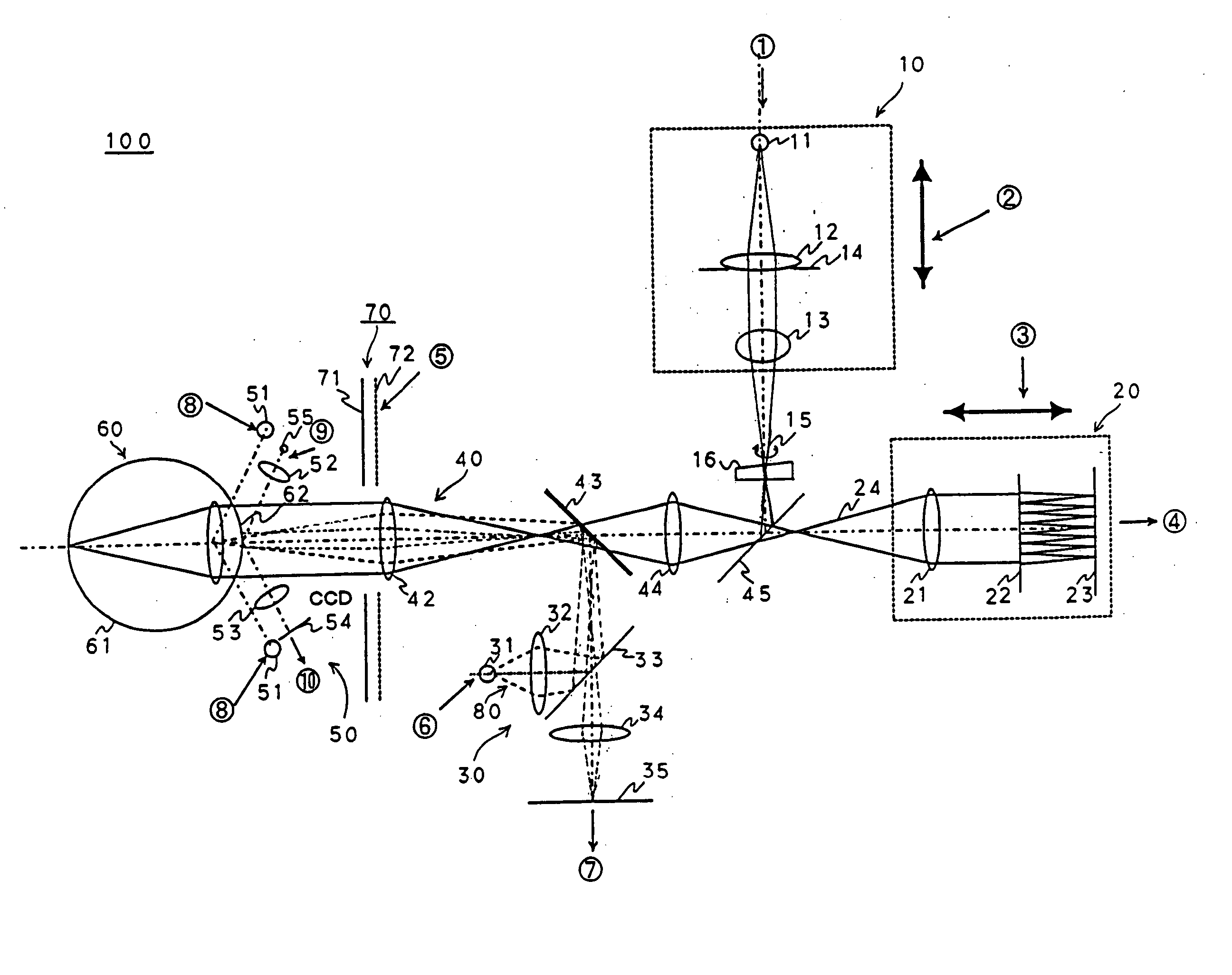
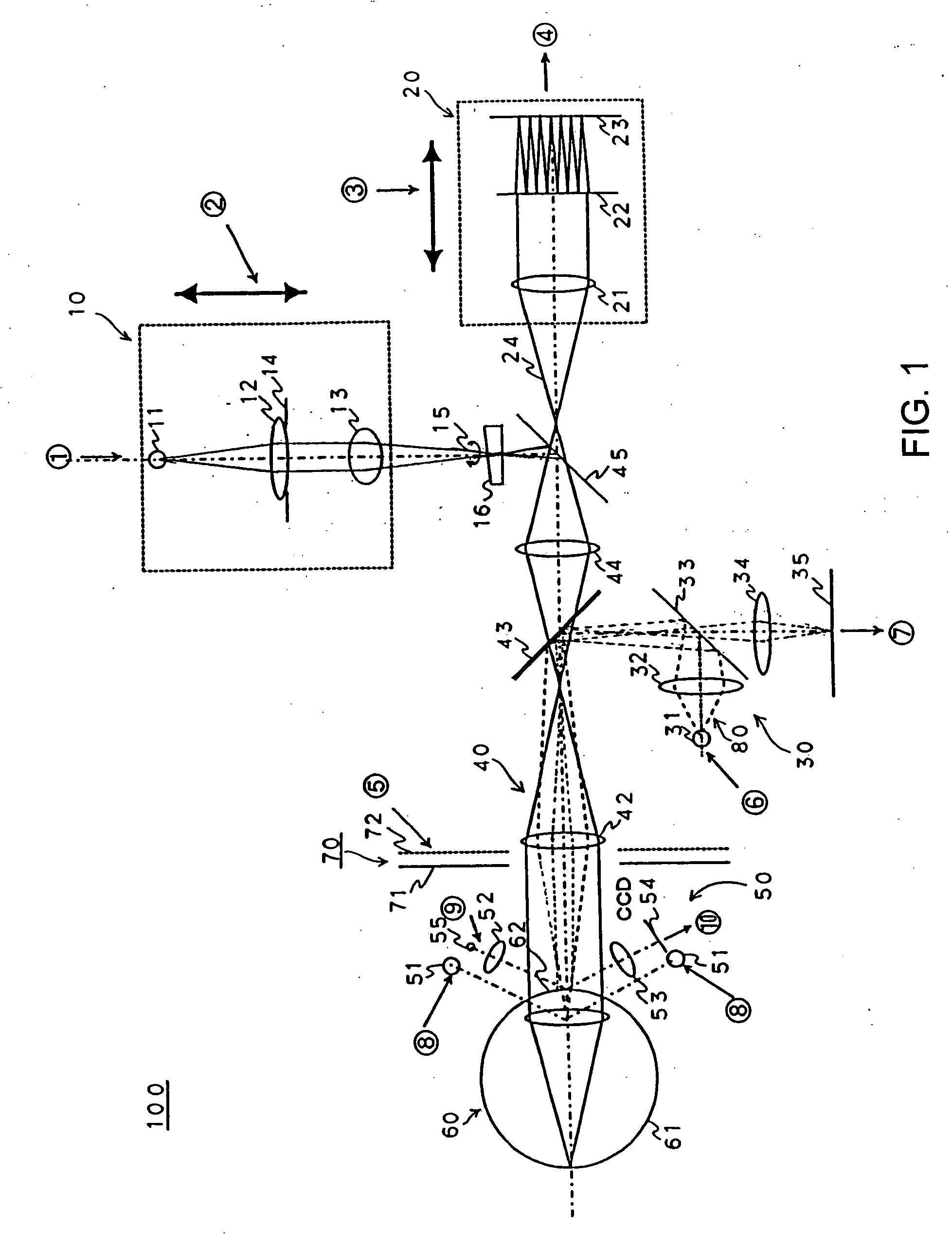
[0047]FIG. 1 is a view showing an outline optical system 100 of an eye optical characteristic measuring apparatus according to the present invention.

[0048] The optical system 100 of the eye optical characteristic measuring apparatus is, for example, an apparatus for measuring an optical characteristic of an eye 60 to be measured as an object, and includes a first illuminating optical system 10, a first light receiving optical system 20, a second light receiving optical system 30, a common optical system 40, an adjusting optical system 50, a second illuminating optical system 70, and a second light sending optical system 80. Incidentally, with respect to the eye 60 to be measured, a retina 61 and a cornea 62 are shown in the drawing.

[0049] The first illuminating optical system 10 includes, for example, a first light source part 11 for emitting a light flux of a first wavelength, and a condensing lens 12, and is for illuminating a m...


PUM


Abstract

In an ophthalmological apparatus, how scattering at an eye under measurement and a contact lens affects how the eye sees is shown by measuring scattering when the contact lens is worn and by comparing a retinal image obtained with aberration and the scattering taken into account and a retinal image obtained with only the aberration taken into account. An aberration measurement section obtains the aberration of the eye under measurement. An other-components measurement section obtains other components other than the aberration component based on a point light-source image caused by each Hartmann plate. A scattering-level calculation section obtains a coefficient expressing the level of scattering based on the other components and the aberration. A simulation section generates a retinal image or data indicating how the eye under measurement sees with the measured aberration and the other components taken into account, based on the aberration and the coefficient.

Description

BACKGROUND OF THE INVENTION [0001] 1. Field of the Invention [0002] The present invention relates to ophthalmological apparatuses. [0003] 2. Description of the Related Art [0004] Conventionally, as a technique for measuring ocular correction data, measurement of S (Sphere), C (Cylinder) and A (axis) by a refractometer has been carried out. Besides, recently, an eye characteristic measuring apparatus capable of measuring higher order aberrations has also been developed, and not only S, C and A on a line like, for example, a ring of φ3 mm as in a refractometer, but also S, C and A on a plane when a pupil diameter is made various sizes can be calculated from lower order aberrations. By the eye characteristic measuring apparatus like this, especially after a refraction correcting surgical operation or in an eye disease, values closer to prescription values of eyeglasses or contact lenses than the refractometer can be calculated (for example, see Patent document 1-4 described followings ...

Claims


Application Information

Patent Timeline
Patent Type & Authority Applications(United States)
IPC IPC(8): A61B3/10A61B3/00A61B3/032A61B3/103A61B3/125A61B3/13A61B3/18
CPCA61B3/032A61B3/125A61B3/1015A61B3/0025A61B3/13A61B3/18
Inventor HIROHARA, YOKO
Owner KK TOPCON
Learn More