Electronic apparatus and cooling medium replacement cartridge

a technology for electronic equipment and cooling medium, applied in the field of electronic equipment, can solve the problems of air-cooling type limitation in heat radiation capability, easy damage to optical modulators and optical components, and easy damage to optical modulators and optical components, and achieve the effect of simplifying the replacement operation of cooling medium

Active Publication Date: 2005-10-06
SEIKO EPSON CORP
View PDF0 Cites 18 Cited by
  • Summary
  • Abstract
  • Description
  • Claims
  • Application Information

AI Technical Summary

Benefits of technology

[0023] According to the present invention, the cooling medium circulated in the electronic apparatus can be replaced with a new one using one cooling medium replacement cartridge. In other words, the first storage section into which the cooling medium is discharged and second storage section that stores a new cooling medium are provided in one cooling medium replacement cartridge. By connecting the connecting sections connected to the first and second storage sections to the tube joints of the electronic apparatus, the replacement of the cooling medium can be performed. The replacement of the cooling medium is performed by connecting the cooling medium replacement cartridge to the tube joints exposed to the outside of the electronic apparatus, so that replacement operation of the cooling medium can be simplified.

Problems solved by technology

In addition, the optical modulator and optical components are easily affected by heat and therefore subject to heat deterioration.
The heat deterioration of the optical modulator and optical components may adversely affect formation of an optical image to pose a problem for the maintenance of functions of the projector.
However, the air-cooling type has a limitation in its heat radiation capability and needs to rotate the fan at high-speed or needs to use a large-sized fan for the purpose of assuring required air volume, impeding reduction of noise and size of the projector.
Accordingly, if discoloration of the cooling medium is caused due to aging degradation, heat degradation, or the like, or if impurities are introduced into the cooling medium, the discoloration and introduced impurities adversely affect a projection image.
However, complicated works such as disassembly of the projector are required to replace the cooling medium.

Method used


Image

  • Electronic apparatus and cooling medium replacement cartridge
  • Electronic apparatus and cooling medium replacement cartridge
  • Electronic apparatus and cooling medium replacement cartridge

Examples


first exemplary embodiment

[0034] A first exemplary embodiment of the present invention will be described below with reference to the attached drawings.

[0035] (1) Primary Structure of Projector

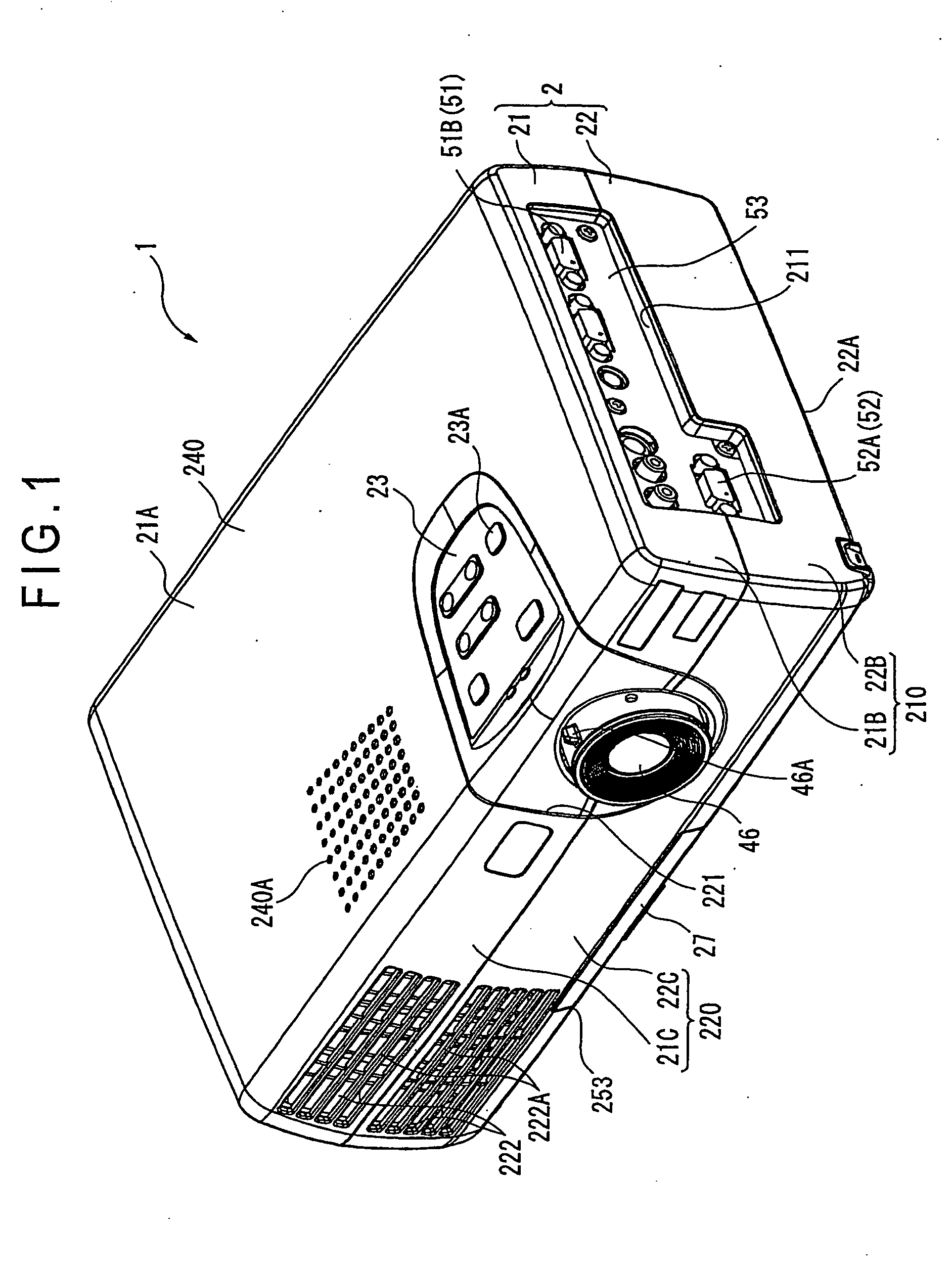
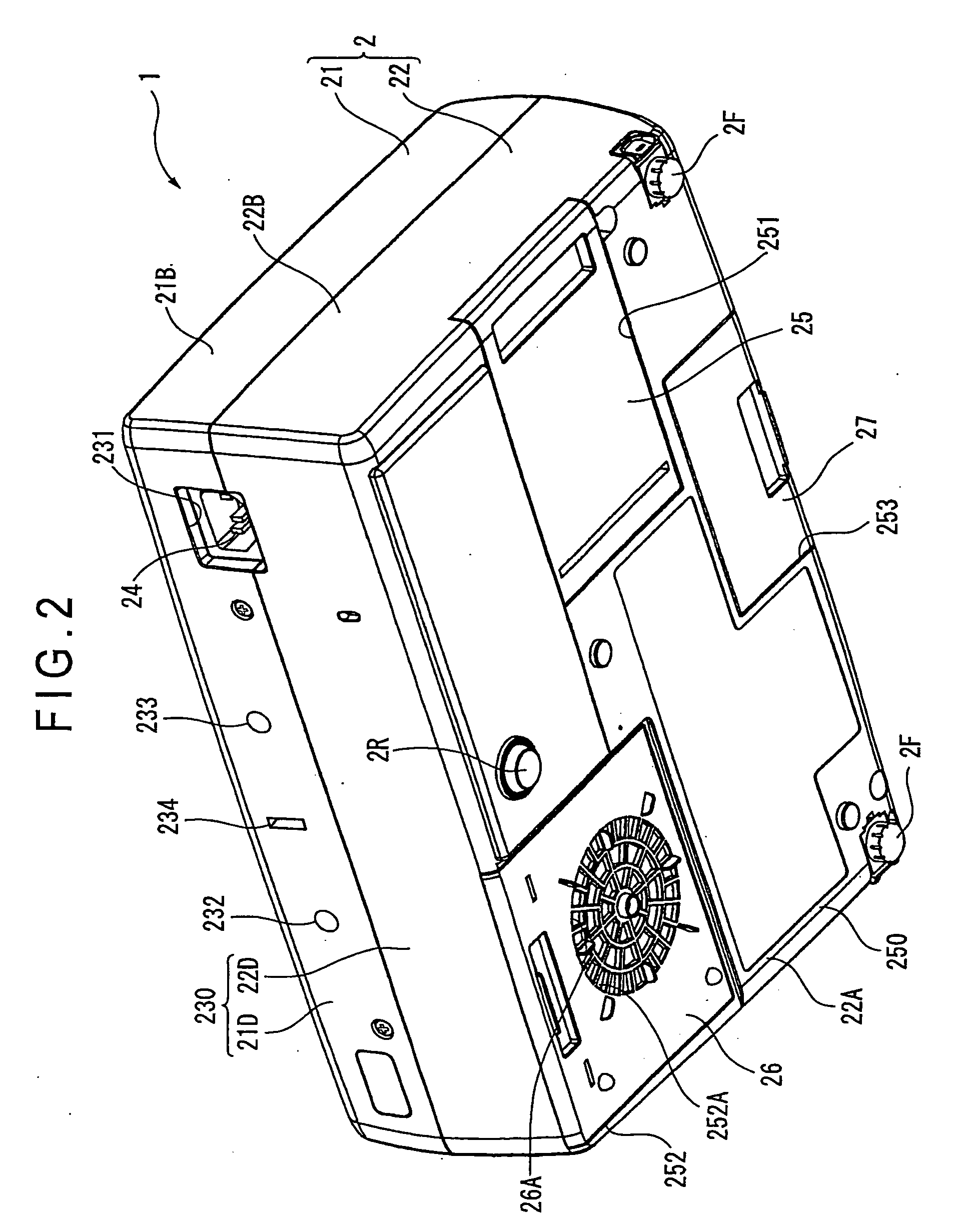
[0036]FIG. 1 is a perspective view of a projector 1 according to the present invention as viewed from upper front side thereof, and FIG. 2 is a perspective view of the projector 1 as viewed from lower rear side thereof.

[0037] As shown in FIG. 1 or 2, the projector 1 includes a substantially rectangular parallelepiped exterior case 2 formed by injection molding. The exterior case 2 is a casing made of synthetic resin and houses an optical unit 4 (FIG. 3) that forms an optical image, a control board (not shown) including a controller that controls drive of the projector 1, a power supply unit (not shown), and a cooling unit 6 that cools components in the projector 1. The exterior case 2 is constituted by an upper case 21 and lower case 22, which are detachably attached to each other.

[0038] As shown in FIGS. 1 and 2, t...

exemplary embodiment

Modification of Exemplary Embodiment

[0159] The present invention is not limited to the above-described exemplary embodiment, and may be modified and altered within a range to achieve the object thereof.

[0160] For example, the supply tube joint 6412 for supplying a new cooling medium and discharge tube joint 6422 for discharging a distributed cooling medium are individually provided in the above exemplary embodiment. Alternatively, however, one tube joint may be used to perform discharge and supply of the cooling medium. In this case, by providing an opening that allows passage of air but blocks passage of the cooling medium in the tube 64, the pressure within the cooling unit 6 can be prevented from being decreased or increased at the time of replacement of the cooling medium. Incidentally, when the supply tube joint 6412 and discharge tube joint 6422 are individually provided in the cooling unit 6 to allow the air sealed in the discharge tank 72 of the cartridge 7 to be distribute...


PUM


Abstract

An electronic apparatus (1) including an apparatus main body and a casing (2) for housing the main body, and further including, inside of the apparatus, a cooling unit (6) that circulates a liquid cooling medium to cool components constituting the main body includes a cooling medium storage section (62) that is provided inside of the casing (2) and stores the cooling medium; a first tube system (641) that guides the cooling medium from the cooling medium storage section (62) to the components to be cooled; a second tube system (642) that sends back the cooling medium having been used for cooling the components to be cooled to the cooling medium storage section (62); and a medium circulator (63) that is disposed on the first tube system (641) or second (642) in order to circulate the cooling medium through the cooling medium storage section (62), first tube system (641), and second tube system (642). Tube joints (6412) (6422) that is exposed to the outside of the casing (2), to which a cooling medium replacement cartridge (7) used for replacing the cooling medium in the cooling medium storage section with a new cooling medium is connected are provided in the first tube system (641) and/or second tube system (642).

Description

BACKGROUND OF TH INVENTION [0001] 1. Field of the Invention [0002] The present invention relates to an electronic apparatus including a main body of the apparatus and a case for housing the main body and further including, inside of the apparatus, a cooling unit that circulates a liquid cooling medium to cool components constituting the main body, and a cooling medium replacement cartridge used for the electronic apparatus. [0003] 2. Description of Related Art [0004] Projectors have been used for presentation in meetings, academic conferences, exhibitions, or the like, or to watch movies at home. A projector of this type includes a light source, a optical modulator that modulates a light beam emitted from the light source in accordance with image information to form an optical image, and an optical device disposed on the upstream and downstream of the optical modulator and having a plurality of optical components that perform optical conversion of an incident light beam. The project...

Claims


Application Information

Patent Timeline
Patent Type & Authority Applications(United States)
IPC IPC(8): G03B21/16G03B21/00G03B21/18G03B21/20H04N5/74
CPCG03B21/20G03B21/16H04N9/3141
Inventor KITABAYASHI, MASASHI
Owner SEIKO EPSON CORP
Why Eureka
Try Eureka