
Wireless communication system and wireless communication method

a wireless communication and wireless communication technology, applied in the field of wireless communication systems, can solve problems such as insufficient user convenience in use, and achieve the effect of high user convenien

Inactive Publication Date: 2005-10-06
KOKUSA ELECTRIC CO LTD +1
View PDF21 Cites 16 Cited by
  • Summary
  • Abstract
  • Description
  • Claims
  • Application Information

AI Technical Summary

Benefits of technology

The present invention provides a wireless communication system that simplifies the transmission right acquisition operation, such as press button depressing operation, by allowing the user to repetitively execute the transmission right acquisition request. This improves user convenience in use and allows the system to better inform the user of the execution result of the transmission right acquisition request. The mobile station in the wireless communication system includes an order accepting section and a control section. The control section conducts wireless transmission of a request for acquiring the transmission right and receives an order from the order accepting section. The control section is adapted to execute the request again if it fails to acquire the transmission right. The mobile station can also output information about the execution result of the transmission right acquisition request and the user can provide additional information through the transmission right acquisition request. The wireless communication system simplifies the transmission right acquisition process and improves user convenience.

Problems solved by technology

The mobile station in the conventional wireless communication system has such a problem, resulting in insufficient user convenience in use.

Method used


Image

  • Wireless communication system and wireless communication method
  • Wireless communication system and wireless communication method
  • Wireless communication system and wireless communication method

Examples


Embodiment Construction

[0055] Hereafter, embodiments of the present invention will be described with reference to the drawings. The same components are denoted by like reference numerals.

[0056] Ensuing embodiments show the case where the present invention is applied to an FDMA (Frequency Division Multiple Access) narrow band digital mobile communication system according to ARIB STD-T61 which is a wireless communication system.

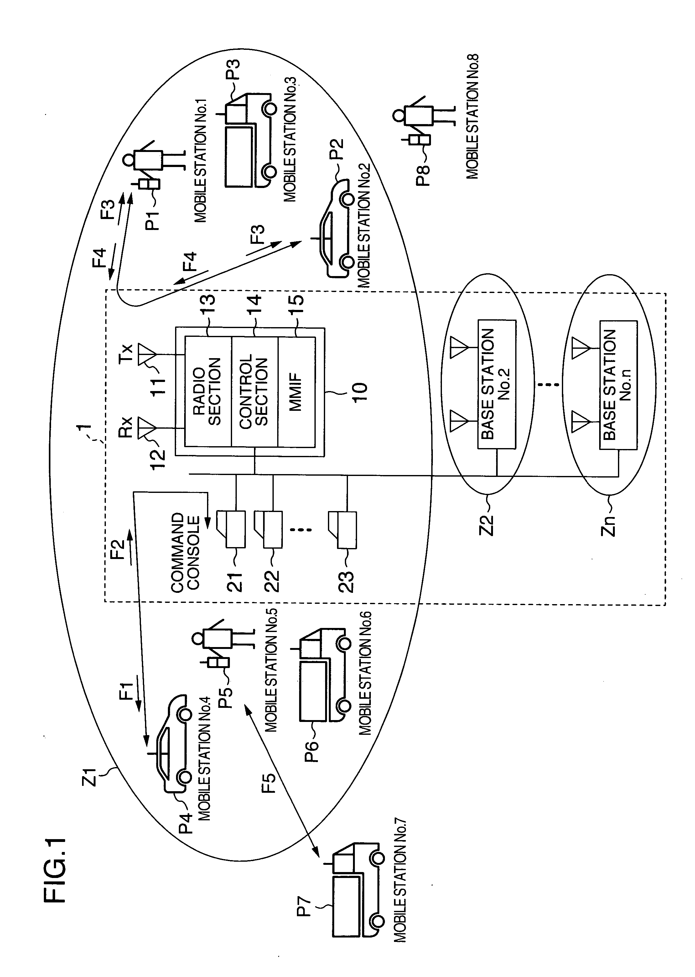
[0057]FIG. 1 shows a configuration of a wireless communication system according to an embodiment of the present invention.

[0058] A wireless communication system according to the present embodiment includes a command console 21, a base station (No. 1) 10 connected to the command console 21 via a wire, and a plurality of mobile stations (mobile station No. 1 to mobile station No. 8) P1 to P8 subordinate to the base station 1.

[0059] In the example shown in FIG. 1, mobile stations (mobile stations No. 1 to No. 6) P1 to P6 which are present in a communication region (base station zone...


PUM


Abstract

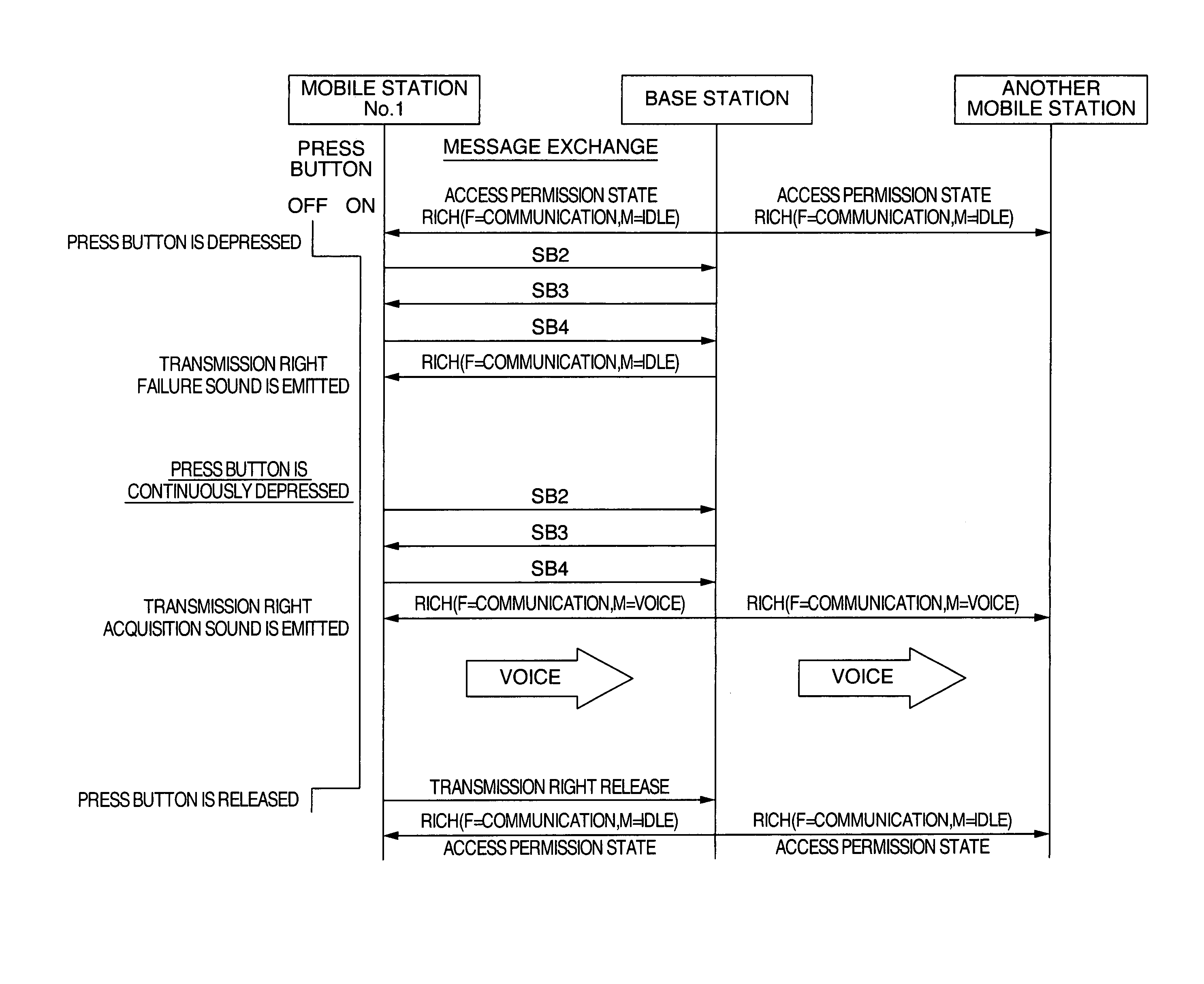
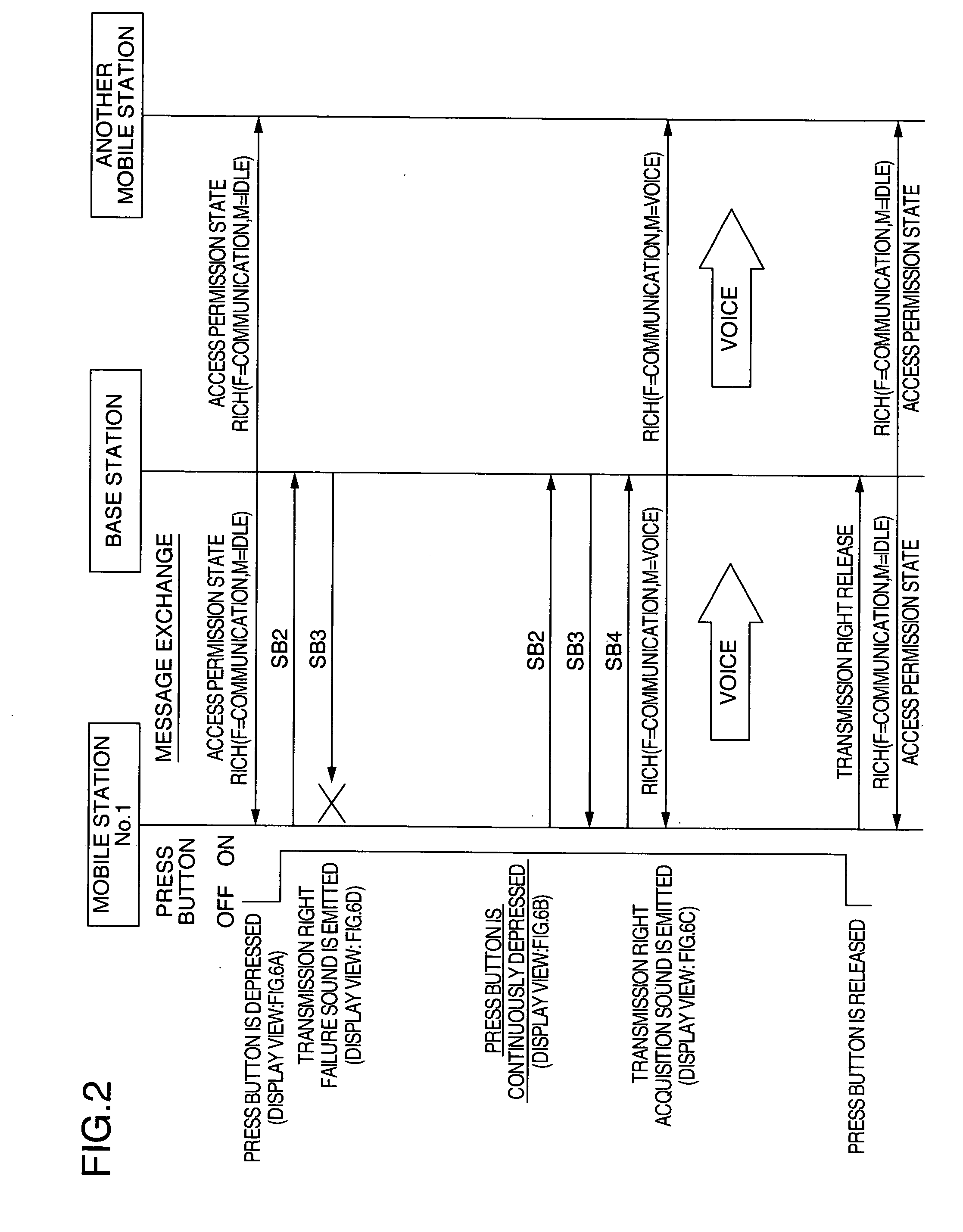
A wireless communication system consisting of a base station and a plurality of mobile stations capable of conducting wireless communication with the base station. Each mobile station has a press button which accepts an order issued by an operator to execute a request for acquiring a transmission right, and a control section. The press button maintains depression electrically or mechanically. The control section in each of the mobile stations is adapted to execute a request for acquiring the transmission right, in response to acceptance of an order conducted by the press button. If the control section fails in acquiring the transmission right by executing the request, the control section is adapted to execute the request for acquiring the transmission right again.

Description

CROSS-REFERENCE TO RELATED APPLICATION [0001] This application contains subject matter which is related to the subject matter of U.S. patent application Ser. No. 10 / 403,276, which is assigned to the same assignee as the present application, filed on Apr. 1, 2003 in the names of Masayuki Kanazawa and Masaru Adachi, and entitled “Mobile communication system having a base station and plural mobile stations and communication method therefore”, the subject matter of which is hereby incorporated by reference herein in its entirety.INCORPORATION BY REFERENCE [0002] The present application claims priority from Japanese application JP2004-042525 filed on Feb. 19, 2004, the content of which is hereby incorporated by reference into this application. BACKGROUND OF THE INVENTION [0003] The present invention relates to a wireless communication system in which a mobile station conducts wireless communication with a base station by using the simplex system. In particular, the present invention rela...

Claims


Application Information

Patent Timeline
Patent Type & Authority Applications(United States)
IPC IPC(8): H04B1/54H04B7/26H04W4/06H04W4/10
CPCH04W4/10H04W76/005H04W72/005H04W76/45H04W72/30
Inventor UCHIDA, MINORU
Owner KOKUSA ELECTRIC CO LTD
Learn More