Method and device for placing a unidirectional thread layer on longitudinal conveyors, method for laying weft threads on warp knitting machines, and device to carry out said methods

A technology of weft yarn and yarn layer is applied in the field of devices for laying unidirectional yarn layers to achieve the effects of increased speed and great mobility

Inactive Publication Date: 2009-09-09
LIBA MASCHFAB
View PDF6 Cites 11 Cited by
  • Summary
  • Abstract
  • Description
  • Claims
  • Application Information

AI Technical Summary

Problems solved by technology

If the movement of the longitudinal conveyor belt, the thread guide and the displacement rake is driven and controlled separately by means of servo motors according to DE 102 07 317 C1, the said disadvantages caused by the system constraints are still not fundamentally changed

Method used


Image

  • Method and device for placing a unidirectional thread layer on longitudinal conveyors, method for laying weft threads on warp knitting machines, and device to carry out said methods
  • Method and device for placing a unidirectional thread layer on longitudinal conveyors, method for laying weft threads on warp knitting machines, and device to carry out said methods
  • Method and device for placing a unidirectional thread layer on longitudinal conveyors, method for laying weft threads on warp knitting machines, and device to carry out said methods

Examples


Embodiment Construction

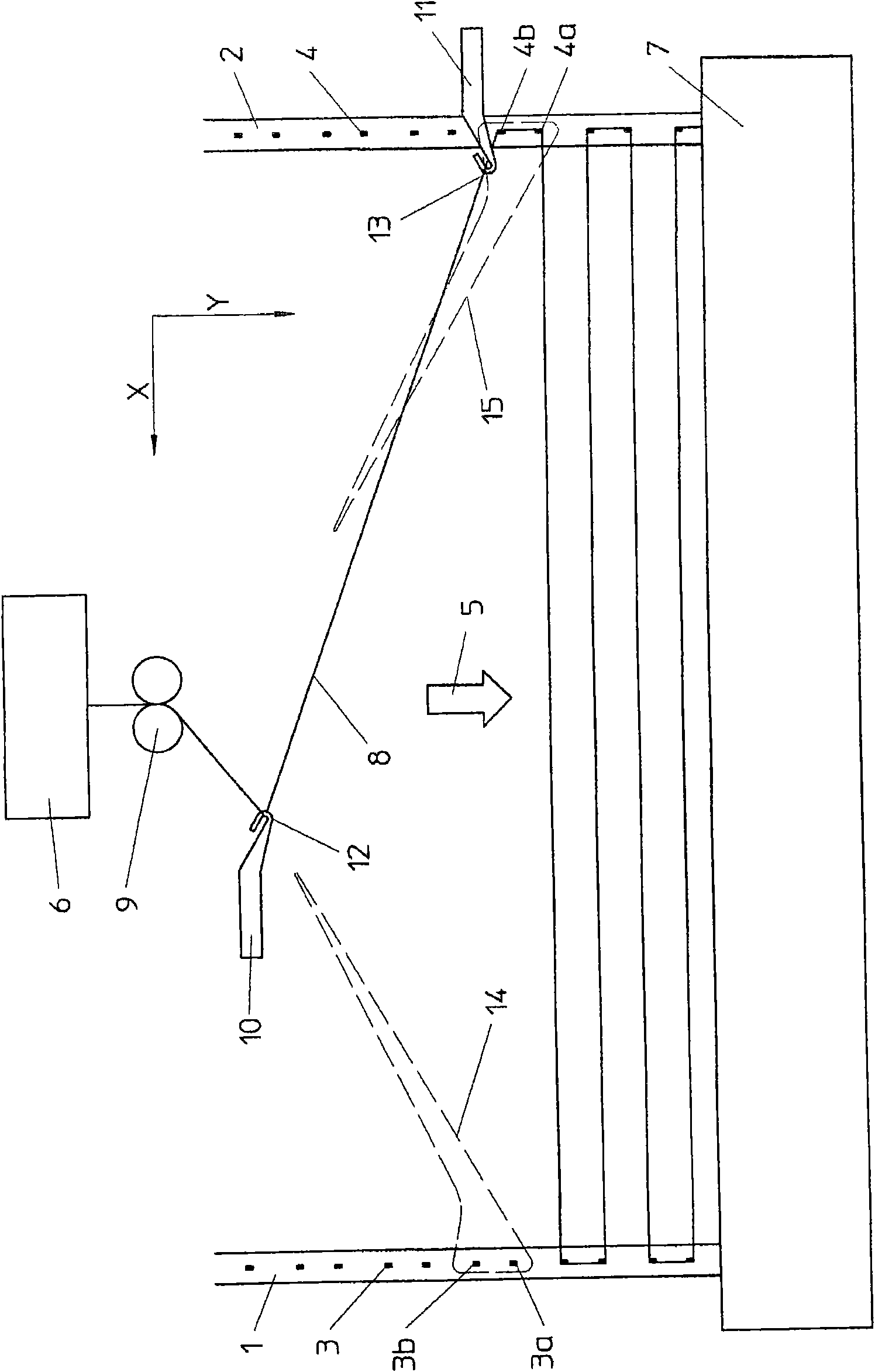
[0047] figure 1 A schematic diagram showing the laying of a unidirectional layer with a not very large width according to the method of the present invention is shown. The process of laying a single thread 8 in a zigzag-shaped parallel store is shown as an example. Two spaced apart driven longitudinal conveyor belts 1 and 2 have fastening hooks 3 and 4 . The longitudinal conveyor belts 1 , 2 move continuously in the conveying direction 5 . In practice, the longitudinal conveyor belts 1, 2 consist of conveyor chains, only the upper branches of which are visible in the figure.

[0048] With the arrangement shown, an infinite number of yarns 8 are delivered from the storage device 6 to the knitting station 7 . The storage device 6 may be a bobbin or, in the case of a wire harness, a creel. The yarn 8 leaving the storage device 6 is conveyed to the first yarn feeding device 10 via the deflection pulley 9 . The yarn 8 runs from here to the second thread delivery device 11 . T...


PUM


Abstract

In the warp knitting machines and knitting machines for multi-axis must be one-way yarn layer (8) to mobile vertical conveyor belt installation (1,2) and hung on the conveyor belt at the vertical (1,2) on a fixed set of hooks (3 , 3a, 3b, or 4,4a, 4b) on the. Above the vertical conveyor (1,2) to send the direction (5) mobile. Described yarn (8) from the storage device (6) was extracted and transferred through the pulley off (9) transmission line to the first input device (10), referred to the input line of the device will hang the yarn to the first vertical conveyor belt (1) a fixed set of hooks (3,3a, 3b) in the. Then, the second transmission line unit (11) will be linked to the second vertical conveyor belt yarn (2) a fixed set of hooks (4,4a, 4b) in the. Described in two transmission-line device (10,11) in two mutually perpendicular extension of the direction of x axis and y-axis movement and the movement to draw a closed orbit (14 and 15). In order to grab yarn (8), referred to the input line of devices (10,11) set up branch with claws (12,13). The methods described can also be achieved through the yarn guide, which referred to the input line of devices (10,11) was designed to shift rake. Yarn made of layers is transported to a warp knitting machine knitting station (7) or knitting tools.

Description

technical field [0001] The invention relates to a method for laying layers of unidirectional yarns on two longitudinal conveyor belts, the invention also relates to a method for feeding weft threads to warp knitting machines and a device for laying layers of unidirectional yarns . Background technique [0002] Such methods and devices belong to the prior art. Feeding weft yarns to warp knitting machines is a typical application. The weft threads, which are arranged individually or in bundles, are successively deposited parallel to one another and perpendicular to the longitudinal conveyor belt on said longitudinal conveyor belt and fed to the knitting implements of the warp knitting machine. The weaving takes place here with additional warp threads and possibly ground warp threads. The spacing between individual weft threads or weft bundles can be purposefully set and adjusted in order to achieve the desired pattern proportions. Examples for this first application are de...

Claims


Application Information

Patent Timeline
Patent Type & Authority Applications(China)
IPC IPC(8): D04B27/00D04B27/10D04H3/011D04H3/04
CPCD04H3/011D04H3/04D04B23/12
Inventor 海因里希·门策尔特
Owner LIBA MASCHFAB
Why Eureka
Try Eureka