Fixing device and image forming apparatus

a technology of fixing device and image forming apparatus, which is applied in the direction of electrographic process apparatus, instruments, optics, etc., can solve the problems of large temperature droop, poor fixation for a certain number of recording sheets, and temperature droop, so as to suppress the occurrence of temperature droop and speed up the image forming apparatus

Inactive Publication Date: 2005-10-06
FUJIFILM BUSINESS INNOVATION CORP
View PDF3 Cites 27 Cited by
  • Summary
  • Abstract
  • Description
  • Claims
  • Application Information

AI Technical Summary

Benefits of technology

[0025] As an effect of the invention, it becomes possible to deal with the speeding up of the image forming apparatus and to suppress the occurrence of the temperature droop phenomenon in the fixing device. At the same time, it also becomes possible to stably peel off the recording sheet from the fixing roll side.

Problems solved by technology

Since an elastic layer coated on a core metal of the fixing roll and made of silicone rubber or the like acts as a heat resistor, even if a sufficient amount of heat is supplied from an inside of the fixing roll, a time lag occurs before a heat is transmitted to the surface of the fixing roll, so that this temperature droop phenomenon is caused.
Especially, in cardboard or the like having a large heat capacity, since an amount of heat removed from the surface of the fixing roll becomes large, there is an tendency that the temperature droop becomes large.
Thus, in a case where an attempt is made to further speed up the image forming apparatus, there arises a new problem that poor fixation is apt to occur for a certain number of recording sheets before the surface temperature of the fixing roll is restored.
However, in the case where an attempt is made to speed up the image forming apparatus, when poor peeling once occurs and a jam occurs, the number of subsequent recording sheets damaged by the influence becomes large.

Method used


Image

  • Fixing device and image forming apparatus
  • Fixing device and image forming apparatus
  • Fixing device and image forming apparatus

Examples


embodiment 1

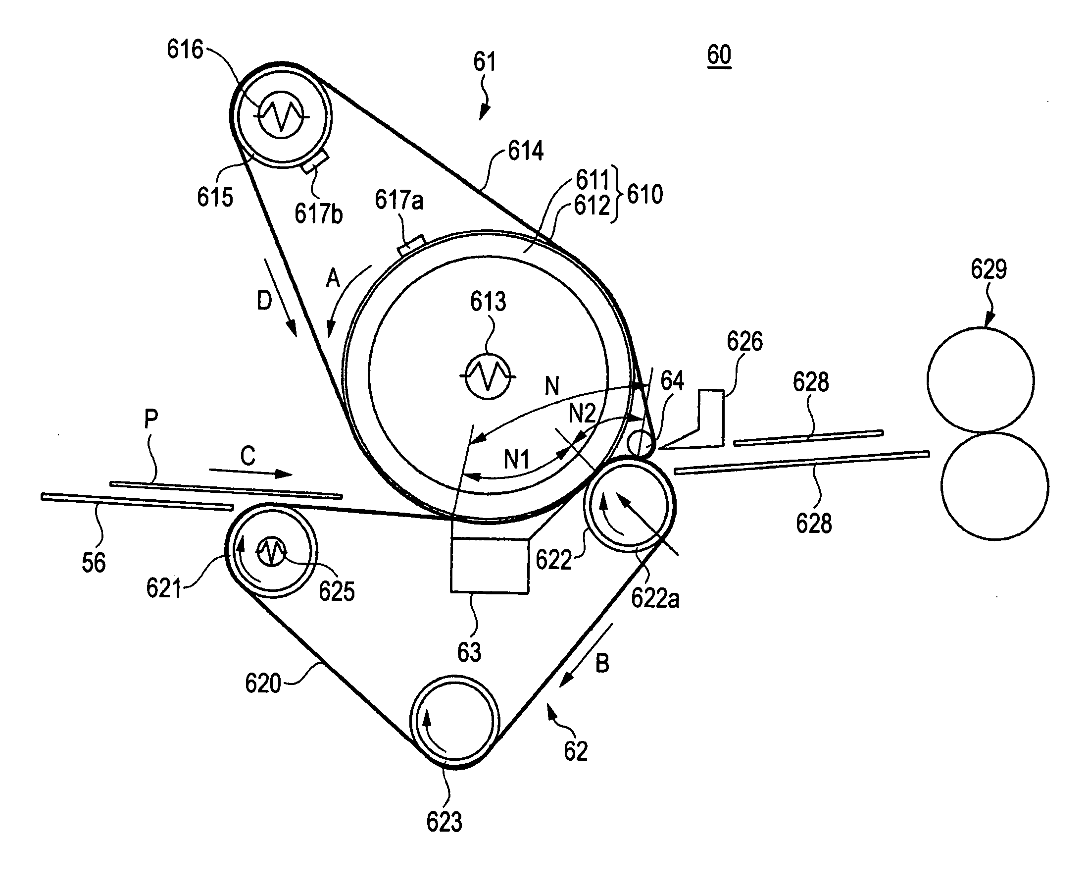
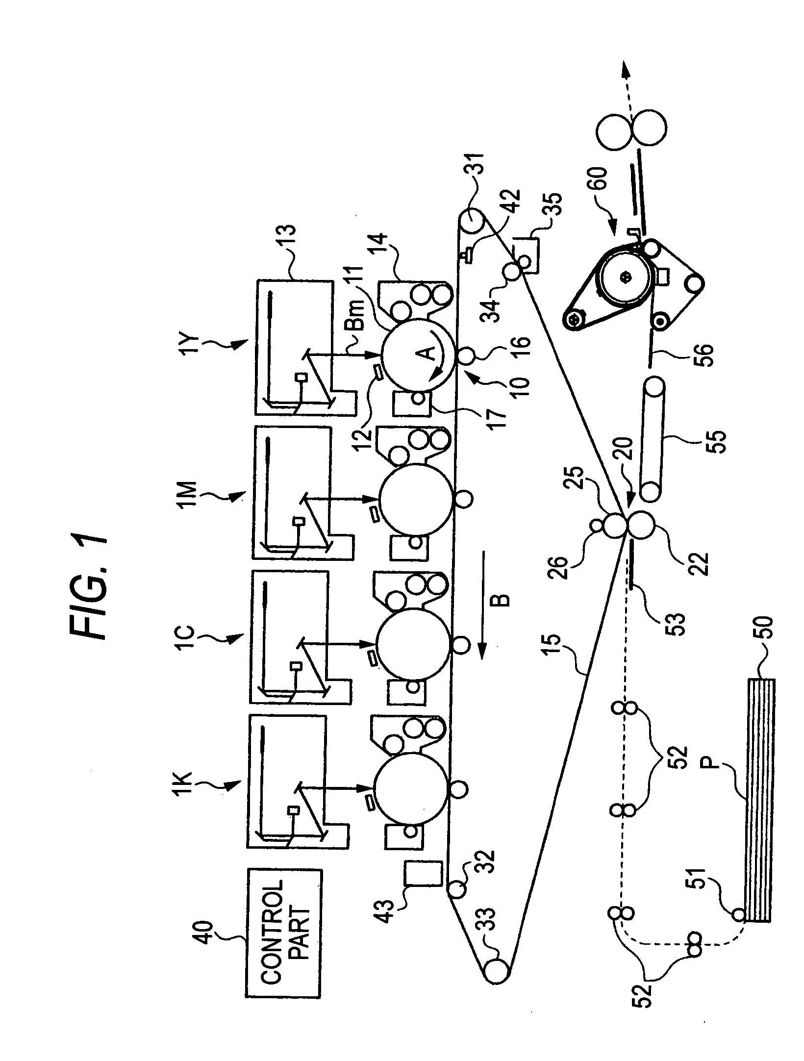
[0034]FIG. 1 is a schematic structural view showing an image forming apparatus to which this embodiment is applied. The image forming apparatus shown in FIG. 1 is an image forming apparatus of an intermediate transfer system generally called a tandem type, and includes plural image formation units 1Y, 1M, 1C and 1K in which toner images of respective color components are formed by an electrophotographic system, a primary transfer part 10 for sequentially transferring (primary transfer) the toner images of the respective color components formed by the image formation units 1Y, 1M, 1C and 1K onto an intermediate transfer belt 15, a secondary transfer part 20 for transferring (secondary transfer) the superimposed toner images transferred on the intermediate transfer belt 15 onto a sheet P as a recording member (recording sheet) at once, and a fixing device 60 for fixing the secondarily transferred image to the sheet P. Besides, a control part 40 for controlling the operation of the res...

embodiment 2

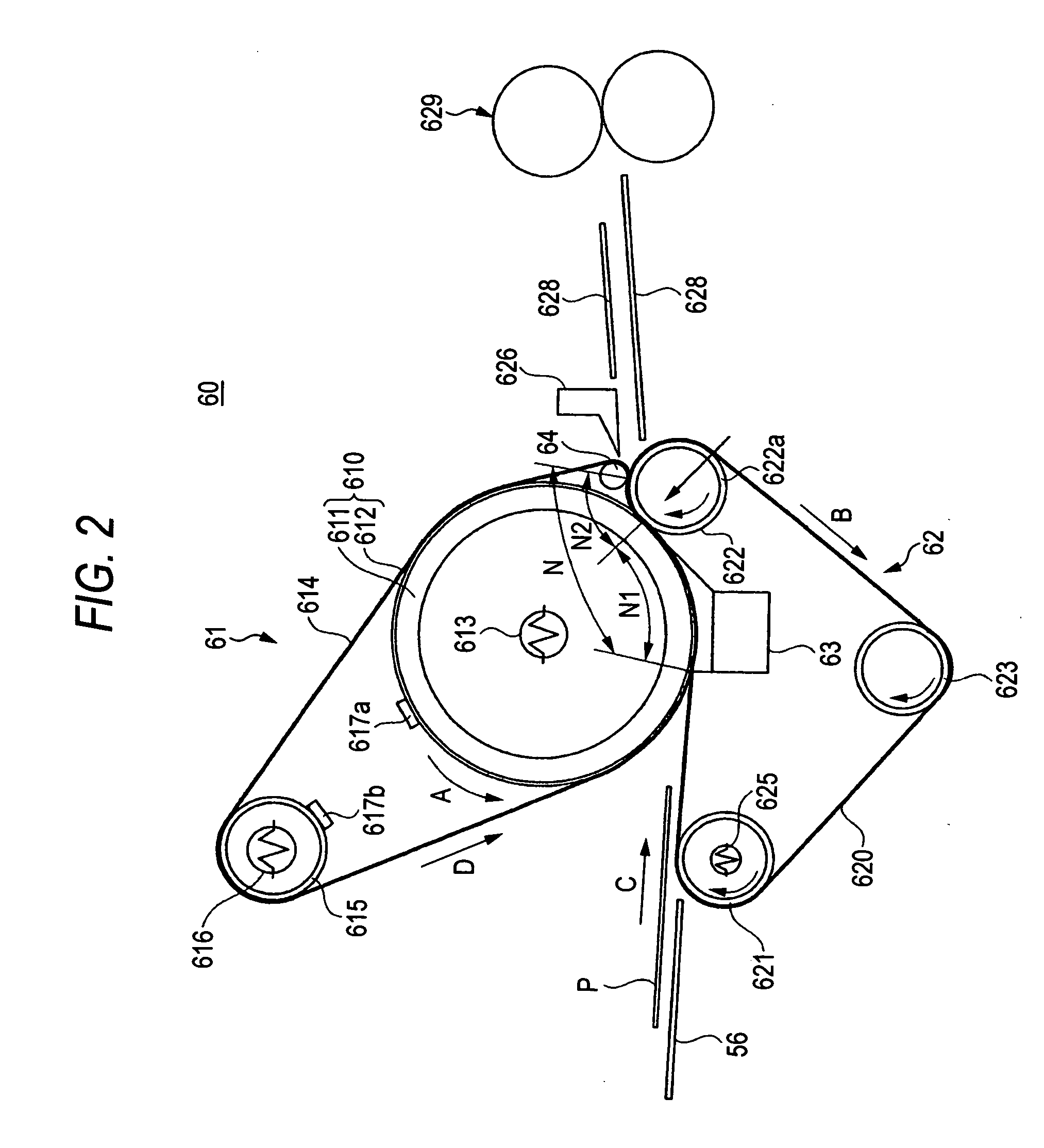
[0103] In embodiment 1, the description has been given to the image forming apparatus including the fixing device 60 having the structure that the stretching roll 615 inside which the halogen heater 616 as the heating member is provided is disposed in parallel to the fixing roll 610, and the endless fixing belt 614 is stretched over the stretching roll 615 and the fixing roll 610. In embodiment 2, a description will be given to a fixing device 70 which is a fixing device mounted in the image forming apparatus shown in FIG. 1 and in which two stretching rolls 615 are disposed, and the one stretching roll newly disposed comes in contact with an outer surface of a fixing belt 614. Incidentally, a similar structure to embodiment 1 is denoted by the same reference numeral and the detailed description will be omitted here.

[0104]FIG. 5 is a side sectional view showing the structure of the fixing device 70 of this embodiment. The fixing device 70 of this embodiment is similar to the fixing...


PUM


Abstract

To provide a fixing device which can suppress the occurrence of a temperature droop phenomenon, and to stably peel off a recording sheet from a fixing roll side. There are provided a fixing belt module and a pressure belt module, and the fixing belt module and the pressure belt module are in contact with each other through a fixing belt and a pressure belt in a first nip portion formed on a fixing roll around which the fixing belt is wound and a second nip portion formed on a pressure roll around which the pressure belt is wound.

Description

BACKGROUND OF THE INVENTION [0001] 1. Field of the Invention [0002] The present invention relates to a fixing device, and more particularly to a fixing device for use in, for example, an image forming apparatus using an electrophotographic system. [0003] 2. Description of the Related Art [0004] In an image forming apparatus, such as a copying machine or a printer, using an electrophotographic system, a photoreceptor (photosensitive drum) formed into, for example, a drum shape is uniformly charged, and the photosensitive drum is exposed with light controlled on the basis of image information to form an electrostatic latent image on the photosensitive drum. This electrostatic latent image is changed to a visible image (toner image) by toner, this toner image is transferred onto a recording sheet, and this is fixed by a fixing device to form an image. [0005] A fixing device used for such an image forming apparatus includes, as shown in FIG. 6, a fixing roll 110 which has a cylindrical ...

Claims


Application Information

Patent Timeline
Patent Type & Authority Applications(United States)
IPC IPC(8): G03G15/20
CPCG03G15/2064G03G2215/2016G03G2215/2009G03G2215/2041G03G2215/2022
Inventor UEHARA, YASUHIROBABA, MOTOFUMIAMANO, JYUNPEIINOUE, TOHRU
Owner FUJIFILM BUSINESS INNOVATION CORP
Why Eureka
Try Eureka