Printing apparatus, printing method, and program

Active Publication Date: 2005-10-06
CASIO COMPUTER CO LTD
View PDF16 Cites 3 Cited by
  • Summary
  • Abstract
  • Description
  • Claims
  • Application Information

AI Technical Summary

Benefits of technology

[0010] Another object of the present invention is to provide a printing apparatus whose consumption power at a print operating time is small and a printing method.
[0011] Further another object of the present i

Problems solved by technology

For this reason, when this apparatus is used as peripheral equipment of the computer system, there is a problem that the space for installment becomes large.
Moreover, such a complicated task

Method used


Image

  • Printing apparatus, printing method, and program
  • Printing apparatus, printing method, and program
  • Printing apparatus, printing method, and program

Examples


Example

[0069] (First Embodiment)

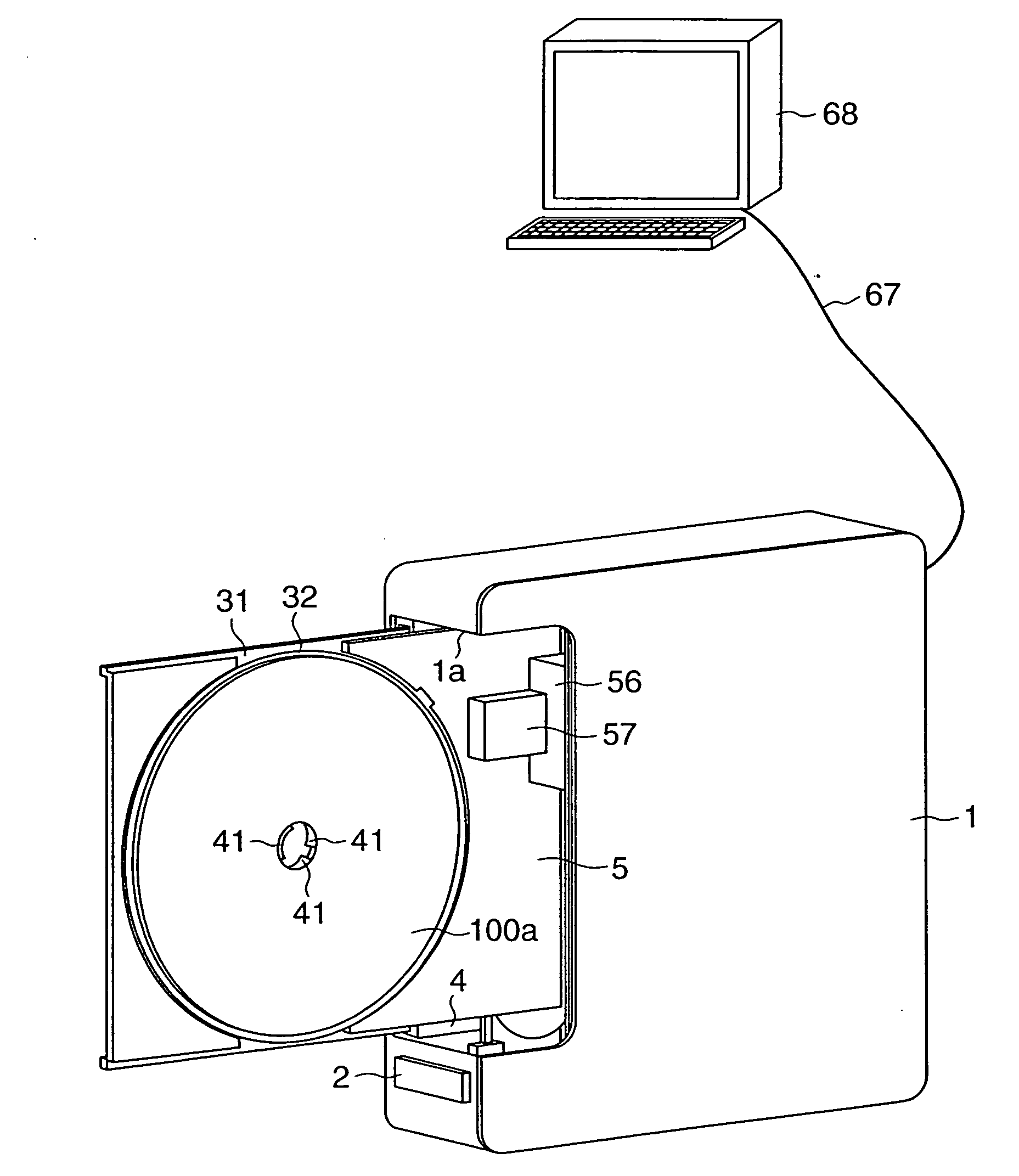
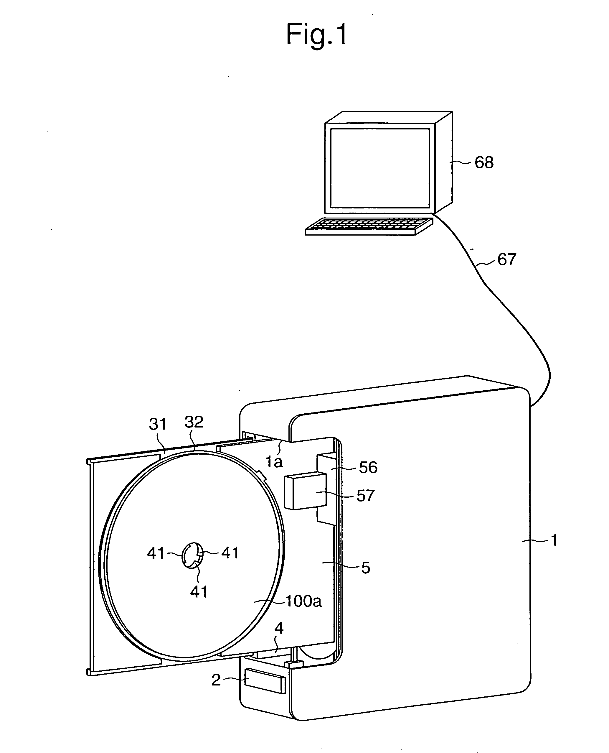
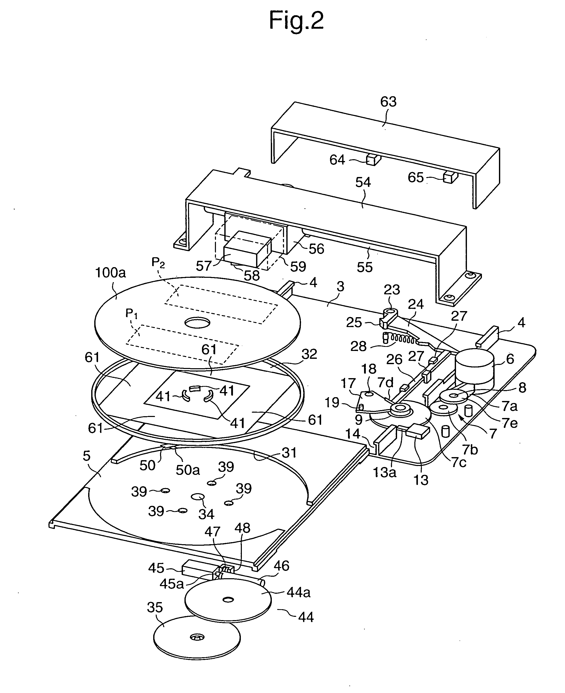
[0070]FIG. 1 is a perspective view of the entirety of a printing apparatus according to a first embodiment; FIG. 2 is an exploded perspective view of the main parts of the printing apparatus, and FIGS. 3 and 4 are views each showing a plane structural view of the main parts.

[0071] Additionally, the printing apparatus according to this embodiment can be used both horizontally and vertically. FIGS. 3 and 4 are plane views when the printing apparatus is placed horizontally. When the printing apparatus is placed vertically as shown in FIG. 1, a right side surface or a left side surface of a case 1 corresponds to a bottom surface in FIGS. 3 and 4.

[0072] The printing apparatus of this embodiment includes a tray mechanism that supports an optical disk and a printer mechanism that performs printing (label printing) to a surface (label surface) of the optical disk supported by the tray mechanism. This printing apparatus further includes an eject function of ejecti...

Example

[0162] (Second Embodiment)

[0163] An explanation will be next given of the printing apparatus of the second embodiment.

[0164] The printing apparatus of the first embodiment was used to perform printing to the label of the optical disk 100a. The printing apparatus of the second embodiment has the function capable of performing printing to both the label of the optical disk 100a and paper material.

[0165] Generally, as shown in FIG. 9, the optical disk 100a such as CD-R and the like is contained in a transparent case 100b, and paper material 100c such as a cover, jacket, and the like is further contained in the case 100b. The paper material 100c has a rectangular shape whose one side, which is substantially the same length as the diameter of the disk-like optical disk 100c.

[0166] In the printing apparatus of this embodiment, such the optical disk 100a and paper material 100c are used as printing objects. The rotatable base 32 has a circular shape corresponding to the disk-like optic...

Example

[0186] (Third Embodiment)

[0187] An explanation will be next given of the printing apparatus having the apparatus structure which is appropriate to the use in a vertical position.

[0188]FIG. 18 is a perspective view showing the entirety of a printing apparatus according to this embodiment. FIGS. 19 and 20 are a side view and a front view, each showing the structure of the main parts of the printing apparatus.

[0189] This printing apparatus includes a box-shape case 101 with the shorter side at the top as an apparatus main body. On both outer side surfaces of the bottom of the case 101, there is formed a leg portion 102 to stabilize placement to an installing surface. The case 101 is installed uprightly on the installing surface with the leg portion 102 at the bottom.

[0190] A base 103 is provided in the case 101, and a tray 121, which supports an optical disk 170 as a printing object, is provided on the base 103. Moreover, in the case 101, there is provided a printer section 135 tha...


PUM


Abstract

In a case (101) with the shorter side at the top, a tray (121) is placed substantially vertically, an optical disk (170) is substantially vertically supported on the tray (121), and a printer section (135) is provided to be opposite to the tray (121). In the printer section (135), a carriage (141) equipped with a thermal head (142) is structured to be movable vertically along the tray (121). When the carriage (141) moved vertically downward, the thermal head (142) is driven to provide thermal transfer printing of a title and the like, which indicate the contents of data recorded on the optical disk (170), to the surface thereof through an ink ribbon (162).

Description

TECHNICAL FIELD [0001] The present invention relates to a printing apparatus, printing method, and a program for printing information such as a title and the like of data recorded on a recording medium on the surface of the recording medium such as an optical disk and the like as a printing object. BACKGROUND ART [0002] Conventionally, the applicant of this invention has proposed printing apparatuses that print a title of an optical disk such as CD-R (Compact Disk-Recordable) on its surface, and put them on the market in Japan. [0003] This type of printing apparatus includes a tray that supports a disk and a printer mechanism that performs printing to the disk supported by the tray. The tray is moved to an external section of an apparatus main body by an eject operation. The printer mechanism performs thermal transfer printing to an optical disk, which is supported on the tray provided at a predetermined position in the apparatus main body and which is in a stationary state, using a...

Claims


Application Information

Patent Timeline
IPC IPC(8): B41J3/407
CPCB41J3/4071B41J3/407B41J11/00B41J2/32B41J2/325
Inventor MOCHIZUKI, YOSHIAKIKIMURA, SATOSHI
Owner CASIO COMPUTER CO LTD
Why Eureka
Try Eureka