Transonic blade profiles

Inactive Publication Date: 2005-10-06
BHARAT HEAVY ELECTRICALS LIMITED
View PDF11 Cites 18 Cited by
  • Summary
  • Abstract
  • Description
  • Claims
  • Application Information

AI Technical Summary

Benefits of technology

[0007] An object of this invention is to propose steam turbine runner blades in tow and intermediate pressure cylinders are of higher height and higher aspect ratio co

Problems solved by technology

Hence the design and manufacturing of twisted blade is costly and time consuming as it is to be done every time for varying flow condition.

Method used


Image

  • Transonic blade profiles
  • Transonic blade profiles
  • Transonic blade profiles

Examples


Embodiment Construction

[0009] According to this invention there is provided a set of six transonic blade profiles comprising each a pressure face and a suction face joined at their leading and trailing edges, the cross sections being twisted over the blade height and that the centers of gravity of these sections lie in a radial line.

BRIEF DESCRIPTION OF DRAWINGS

[0010] The nature of invention, its objective and further advantages residing in the same will be apparent from the following description made with reference to the non-limiting exemplary embodiments of the invention represented in the accompanying drawings.

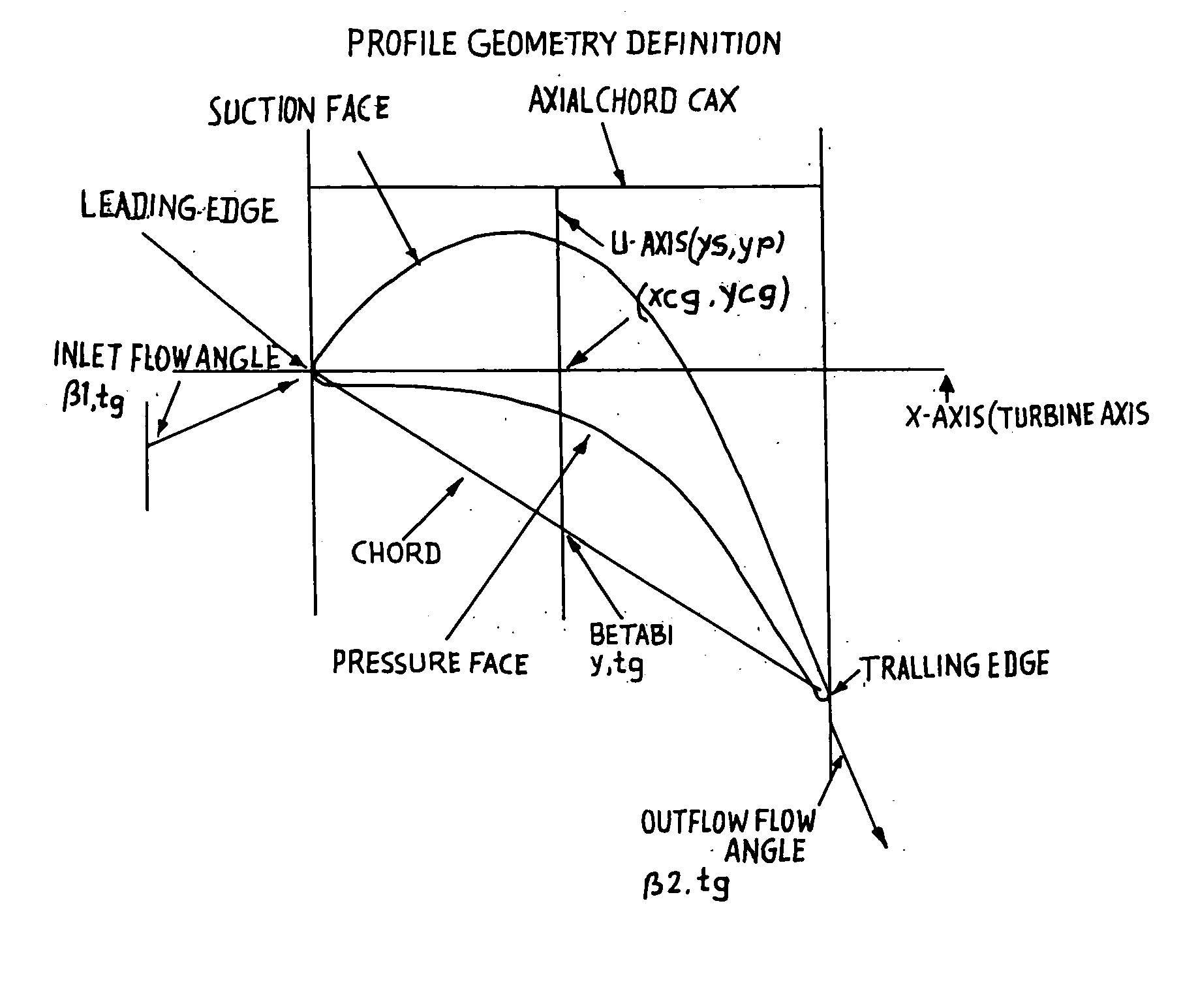
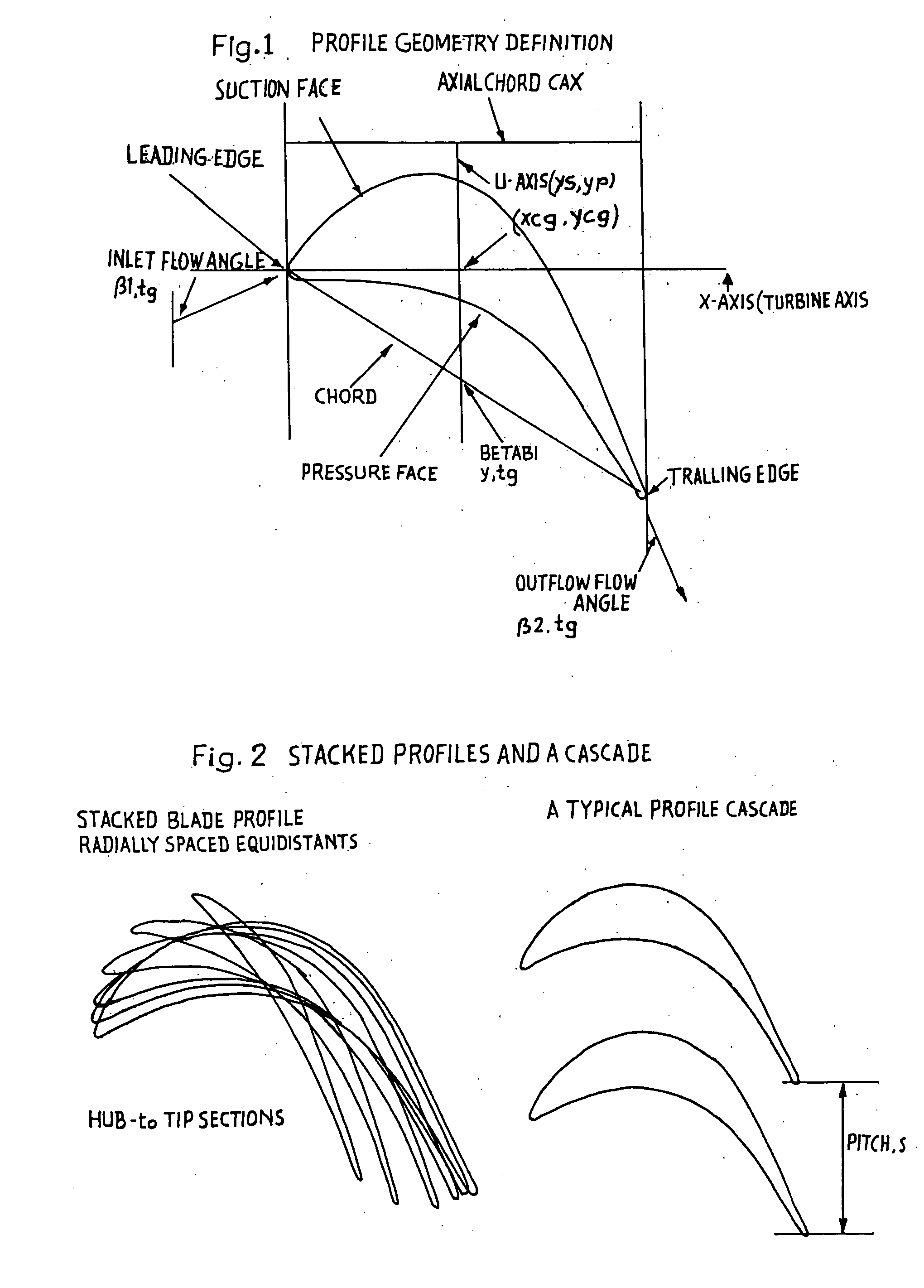
[0011]FIG. 1. Profile Geometry Definition

[0012]FIG. 2. Stacked Profiles and a Cascade

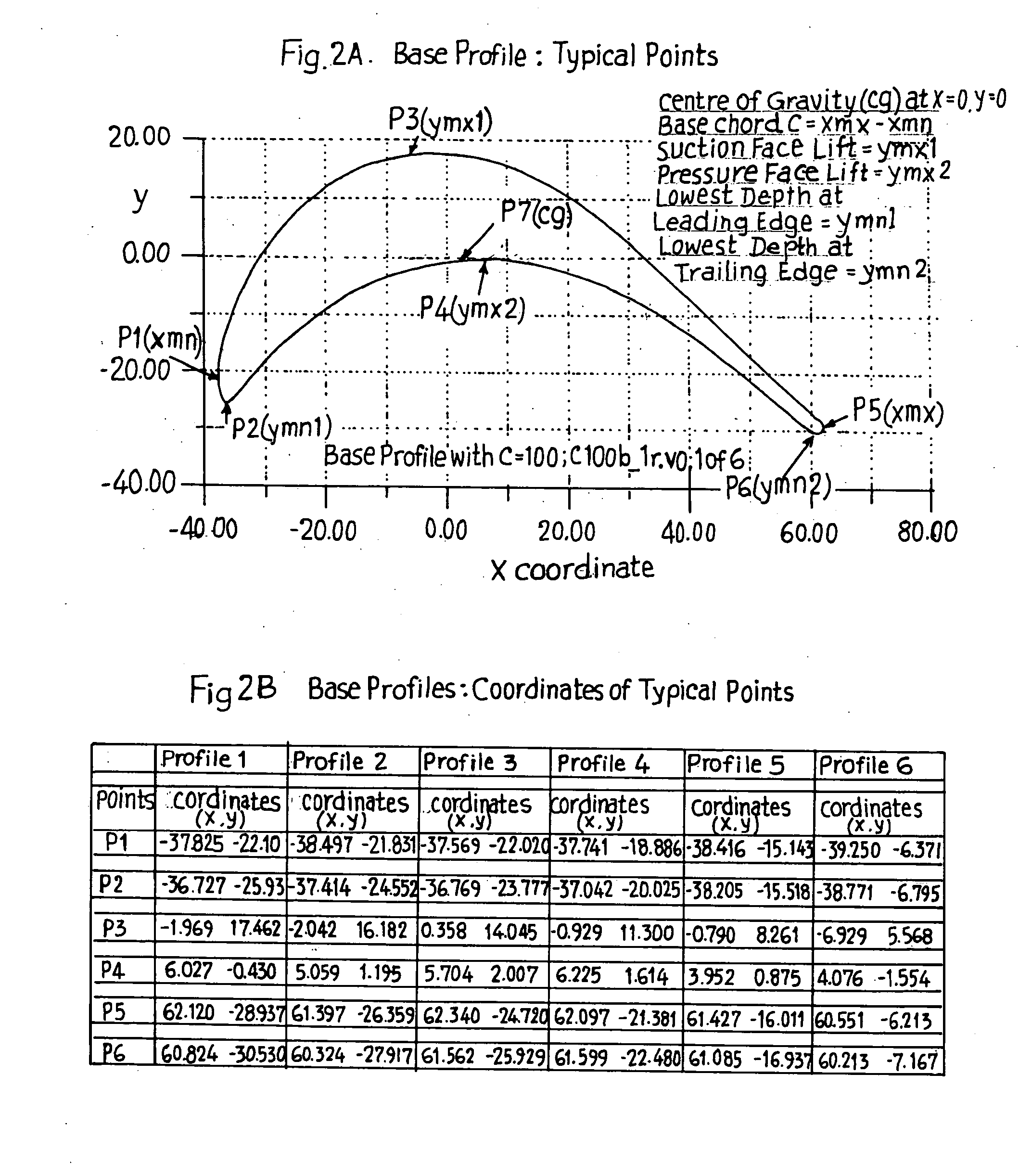
[0013]FIG. 2A. Base Profile: Typical Points

[0014]FIG. 2B. Base Profile: Coordinates of Typical Points

[0015]FIG. 3. Base Profiles: c100b—1r

[0016]FIG. 4. Base Profiles: c100B—1r

[0017]FIG. 5. 3D View of a Typical Blade

[0018]FIG. 6. Nomogram (beta2ax): Profile 1 of c100b—1r

[0019]FIG. 7. Nomogram (zeta): Pr...


PUM


Abstract

The present invention relates to the aerodynamic design of moving blades, pertaining to later stages of axial steam turbines where the inlet flow is non-uniform over the blade height. The claim made herein is a set of six invented transonic blade profiles which can be used to develop various type of 3D twisted blades for axial steam turbine. The aerodynamic characteristics of these 6 base profiles are evaluated herein as a function of stagger angle and pitch / chord ratios. The aerodynamic characteristics invented herein is for a group of six base profiles which are to be used for creation of three dimensional blades made of varying cross-sections and twisted over the blade height while ensuring the centers of gravity of these sections lie in a radial line. Each of the blades, sections from hub to tip is twisted differently from desired outlet angle. Thus the nomograms can be used to develop quickly a first level design of a 3D blade making use of 2D base profiles whose performance is shown in the form of nomograms.

Description

FIELD OF INVENTION [0001] This invention relates to transonic blade profiles for development of 3D twisted blades for axial steam turbine. BACKGROUND OF THE INVENTION [0002] The design of 2D (referred as 2D or cylindrical blade having identical cross-section throughout the blade span) and 3D blades are of paramount importance for power generation. Various patents, e.g. U.S. Pat. No. 5,779,443 (1998), U.S. Pat. No. 5,211,703 (1993) and U.S. Pat. No. 5,192,190 (1993) refer to “stationary” blade. U.S. Pat. No. 5,779,443 deals with radially bent blade (radial shift of centers of areas of individual profiles over the blade height). The present investigation refers to design of six base profiles and construction of moving blade (by making use of these base profiles) without radial shift. [0003] In cylindrical stages, the profiles remain same for more than one stage over their blade height without significant loss in efficiency. The inlet flow is more or less uniform over the Wad height. U...

Claims


Application Information

Patent Timeline
IPC IPC(8): F01D5/14B63H1/26
CPCF01D5/141F05D2250/74F05D2220/80F05D2250/70Y10S416/02Y10S416/05
Inventor CHANDRAKER, A. L.
Owner BHARAT HEAVY ELECTRICALS LIMITED
Why Eureka
Try Eureka