
Light-pipe system for lighting, ventilation and photocatalytic air purification

a technology of light-pipe system and photocatalytic air purification, which is applied in the direction of sky-light/dome, chemical/physical/physical-chemical processes, energy-based chemical/physical/physical processes, etc., can solve the problems of affecting the transmission efficiency of light, too large system, and inconvenient installation

Inactive Publication Date: 2005-10-06
BEIJING UNIV OF TECH
View PDF3 Cites 26 Cited by
  • Summary
  • Abstract
  • Description
  • Claims
  • Application Information

AI Technical Summary

Benefits of technology

[0010] (i) an outside collector (usually on the roof), generally a clear dome that removes UV radiation and acts as a cap to prevent dust and water from entering the pipe;

Problems solved by technology

The transmission efficiency was highly improved but costs were too great.
But this system is too large and complex.
Thus, after a considerable period of time, the dust will deposit in the duct, which will surely affect the transmission efficiency of light.
So, it needs routine cleaning and thus increases maintenance cost.

Method used


Image

  • Light-pipe system for lighting, ventilation and photocatalytic air purification
  • Light-pipe system for lighting, ventilation and photocatalytic air purification
  • Light-pipe system for lighting, ventilation and photocatalytic air purification

Examples


embodiment 1

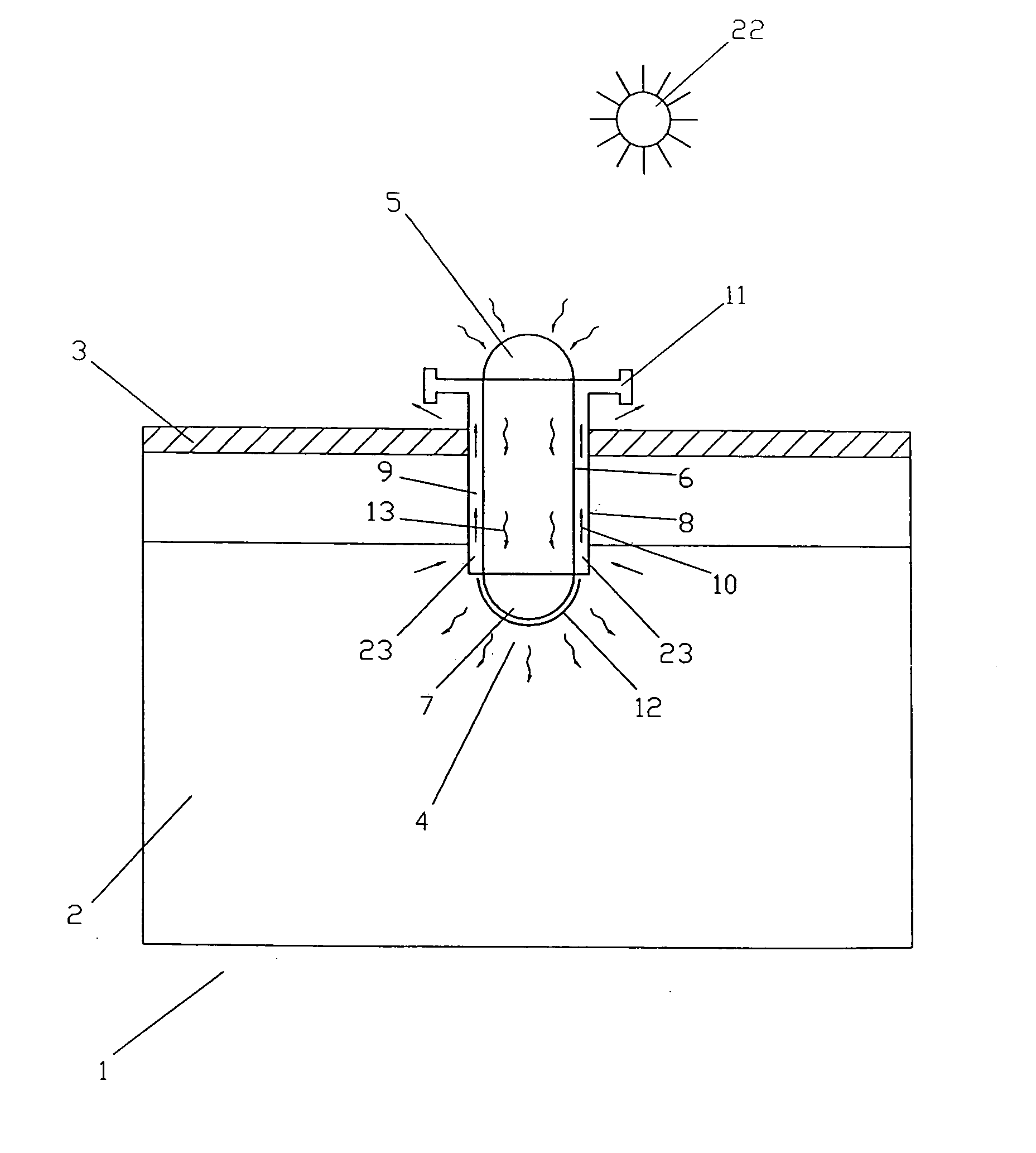
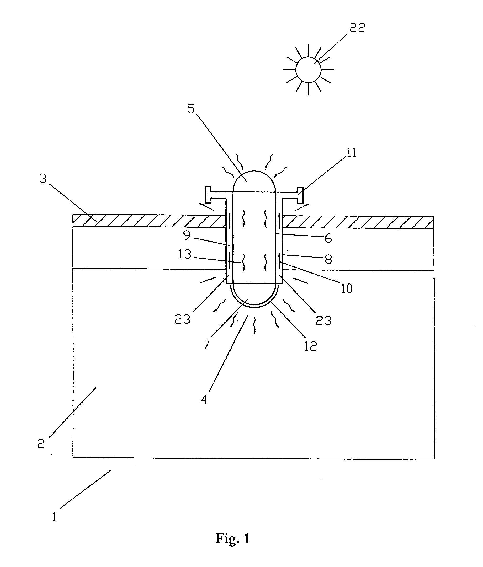
[0048]FIG. 1 shows a building 1 which has at least one room 2 with a roof 3. The light-pipe system 4 for natural ventilation and photocatalytic air purification is installed on the roof 3 of room 2. The light-pipe system 4 comprises a light-pipe device and ventilation stack 8, of which the light-pipe device includes outer light collector 5 for collecting light, light-pipe 6 itself for conducting light and emitter 7 fitted to the bottom of light-pipe 6 for diffusing light and preventing the dust from entering into the interior of the light-pipe 6. The sunlight 22 collected by the light collector 5 of light-pipe 6 is conducted into the interior of building 1. The natural ventilation is achieved along ventilation passage 9 through air port 23 as a result of the temperature difference between indoors and outdoors or the pressure difference due to wind flow around light-pipe outlet. In order to prevent or increase the wind effect, ventilation terminals 11 are used. The nanometer photocat...

embodiment 2

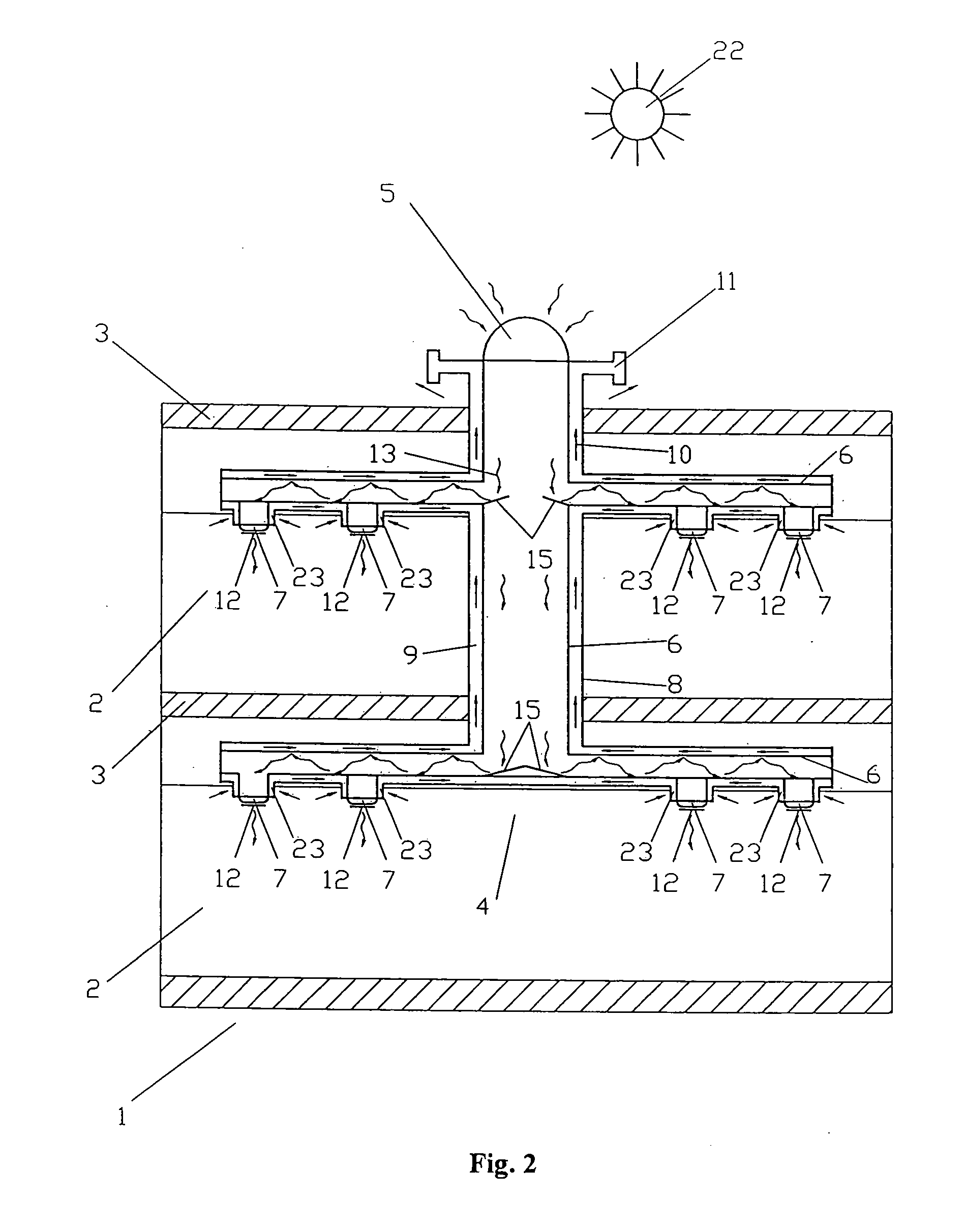
[0050]FIG. 2 shows a building 1 having several rooms 2 with a roof 3. The light-pipe system 4 for natural ventilation and photocatalytic air purification is installed on the roof 3 of room 2. Each room 2 has a horizontal light-pipe 6 connected with vertical light-pipe 6 in the region of its ceiling. The individual horizontal light-pipes 6 are connected to each other by vertical light-pipe 6. Light from the sun 22 passes through the light collector 5 and enters the vertical light-pipe 6. Light is directed into the horizontal light-pipe 6 where it then emerges through light ports (emitter fitted to the light ports) 7. The air port 23 takes up exhaust air, i.e., the room air of the room 2 passes into the corresponding horizontal air passage 9 within wall 8 and, then passes out of the room 2 from ventilation terminals 11 via the central vertical air passage 9 through chimney-like action. The nanometer photocatalyst TiO2 12 is coated on the surface of emitter 7 of light-pipes 6. Under th...

embodiment 3

[0051]FIG. 3 shows a building 1, at least having a room 2 with a roof 3. The light-pipe system 4 for natural ventilation and photocatalytic air purification installed on the roof 3 of room 2 in a manner similar to FIG. 2. The only difference is that artificial lights 14 are installed on the two ends of horizontal light-pipe 6. The light source of light-pipe 6 can be daylight or / and artificial light. The light-pipe system can conduct daylight, artificial lighting, natural ventilation and air purification.


PUM

PropertyMeasurementUnit
Transport propertiesaaaaaaaaaa
Brightnessaaaaaaaaaa
Distributionaaaaaaaaaa

Abstract

The invention relates to a light-pipe system for conducting / distributing light and air, which can also purify indoor air, particularly in a building, or the like. The light-pipe system includes a light-pipe for conducting light and having a clear top dome mounted at the top of the light-pipe to let in sunlight but keep out dust, rain and UV. An emitter fitted to the bottom of light-pipe improves the light distribution into the room, and a ventilation stack laid around the light-pipe coaxially / or non-coaxially, and a photocatalyst film (e.g. Nanometer TiO2) coated on the outer surface of the emitter for purifying indoor air under the illumination of light from light-pipe. The air and light are conducted separately along two different transport paths. The light-pipe system can provide illumination, ventilation and air purification simultaneously. The light source may be daylight, artificial light, light storage material or a mixture of them. Air can be moved naturally and / or is transported mechanically. Mirrors in the light-pipe may be used to control brightness and distribution.

Description

TECHNICAL FIELD [0001] The present invention relates to the technical field of illumination, ventilation and air purification, and more particularly to a light-pipe system through which light and air can be transferred into an indoor room for illumination and air exchange and the indoor air can be purified by irradiating of the light conducted from the light-pipe. BACKGROUND OF THE INVENTION CROSS-RELATED APPLICATIONS [0002] This application claims priority from Chinese Patent Application Serial Nos. 200410029945.2 filed Apr. 6, 2004 and 200410086705.6 filed Oct. 29, 2004, the disclosures of which are incorporated herein by reference. BACKGROUND ART [0003] It is known to conduct or distribute air either in natural flow or mechanical flow in order to ventilate rooms of a building. It is also known to conduct or distribute light, as daylight or artificial light, for instance, to use daylight for illuminating large rooms. [0004] A light-pipe is simply an empty tube along which light ca...

Claims


Application Information

Patent Timeline
IPC IPC(8): B01D53/00B01D53/88B01J19/08E04D13/03F21S8/00F24F3/16F24F13/078
CPCB01D53/007B01D53/885B01D2255/802E04D13/0325E04D13/033Y02A30/272F21S11/00F24F3/16F24F2003/1667F24F2005/0064Y02B10/24E04D2013/0345Y02B10/20F24F8/22F24F7/02F24F8/167
Inventor MA, CHONGFANGLU, YUANWEIWU, YANPENGWU, YUTINGWANG, WEL
Owner BEIJING UNIV OF TECH
Learn More