Vapor reactant source system with choked-flow elements

a technology of reactant source system and vapor reactant, which is applied in the direction of chemical vapor deposition coating, metallic material coating process, coating, etc., can solve the problems of gas flow, gas velocity is choked or limited, and cycles can also be more complex

Inactive Publication Date: 2005-10-06
ASM INTERNATIONAL
View PDF13 Cites 28 Cited by
  • Summary
  • Abstract
  • Description
  • Claims
  • Application Information

AI Technical Summary

Benefits of technology

[0010] According to one aspect of the present invention, an apparatus is provided for providing vapor phase reactants to an atomic layer deposition chamber. The apparatus preferably includes a choked-flow element with an on-off valve and pressure control along a gas flow path between a gas source and an atomic layer deposition chamber. In one embodiment the choked-flow element is an orifice adjacent the on-off valve. In another embodiment the choked-flow element is a capillary insert attached to the on-off valve. The choked-flow element is preferably located immediately upstream of the on-off valve, the on-off valve controlling pulsing to the chamber.
[0011] A method for growing a thin film on a substrate in a reaction chamber by an ALD process is also disclosed. A first reactant source and an inactive gas source are provided. The first reactant is fed from the first reactant source to the reaction chamber. The gaseous first reactant passes through a first choked-flow element and a gas flow control valve prior to entering the chamber. Inactive gas is fed to the reaction chamber from the inactive gas source. Preferably, the choked flow element is adjacent to the gas flow control valve.
[0012] In one embodiment the choked-flow element is an orifice. The orifice may be located upstream of the gas flow control valve. In another embodiment the choked-flow element is a capillary insert attached to the gas flow control valve. The first reactant source may be a solid, liquid or gas.
[0013] A source system for an atomic layer deposition reactor is also provided, comprising a first reactant source, an inert gas source, a first gas conduit connected to the first reactant source and a second gas conduit connected to the inert gas source. A first choked-flow element is disposed in the first gas conduit and a second choked-flow element is disposed in the second gas conduit. A reaction chamber is in fluid communication with the first and second gas conduits. The system also comprises a first gas flow control valve, which comprises a first gas inlet, a second gas inlet and a first gas outlet. The first gas inlet is in fluid communication with the first gas conduit and the second gas inlet is in fluid communication with the second gas conduit. The system may also comprise a pressure control device, for controlling the pressure of the first reactant. The system may further comprise additional reactant sources, each having a separate gas conduit and choked-flow element.
[0014] In another aspect the invention provides a gas flow controller comprising a reactant source, an inactive gas source and, a gas flow control valve in fluid communication with and upstream of the reactant source. A choked-flow element is preferably located upstream of the reactant source and a reaction chamber is located downstream of the gas control valve.
[0015] In a further aspect, the invention concerns a method of delivering reactants to a reaction chamber, such as in an atomic layer deposition process. One or more reactant sources are provided. Reactants are fed from the reactant sources through a gas flow conduit into the reaction chamber. A choked-flow condition is established upstream of the reaction chamber.

Problems solved by technology

Sonic conditions result in a gas flow in which the velocity of the gas becomes choked or limited.
Cycles can also be more complex.
ALD source systems for providing the precursors and controlling the purge steps have been rather expensive because of costly mass flow controllers (MFCs) that have been used for adjusting the flow rate of inert carrier gas to the precursor sources.
In ALD systems rapid switching of gases is required, but MFCs often have problems due to rather long internal settling time and pressure fluctuations within source systems are induced.
Such pressure fluctuations are undesirable for a number of reasons, including unwanted reactant interactions, condensation of reactants and particulate generation.

Method used


Image

  • Vapor reactant source system with choked-flow elements
  • Vapor reactant source system with choked-flow elements
  • Vapor reactant source system with choked-flow elements

Examples


Embodiment Construction

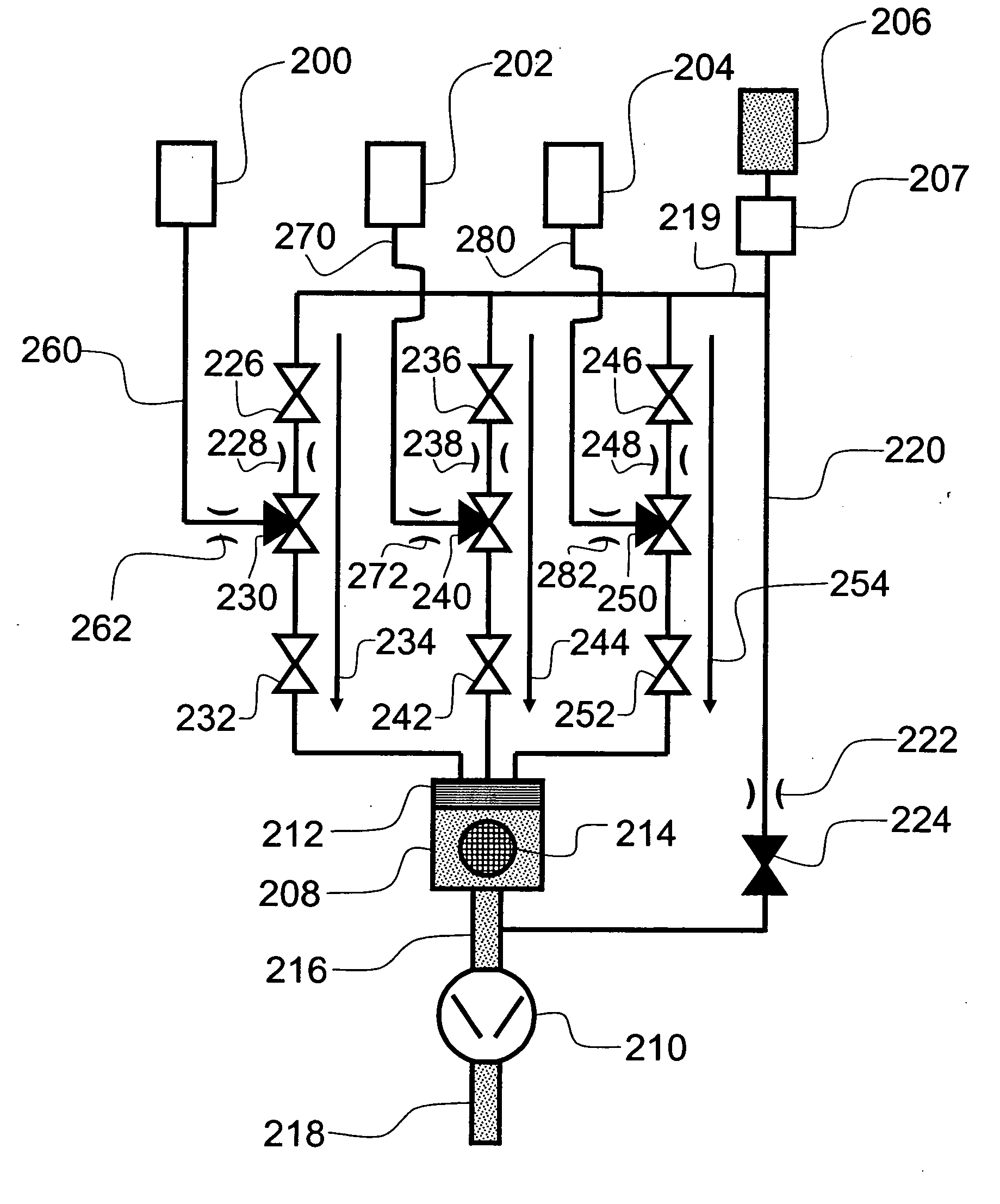
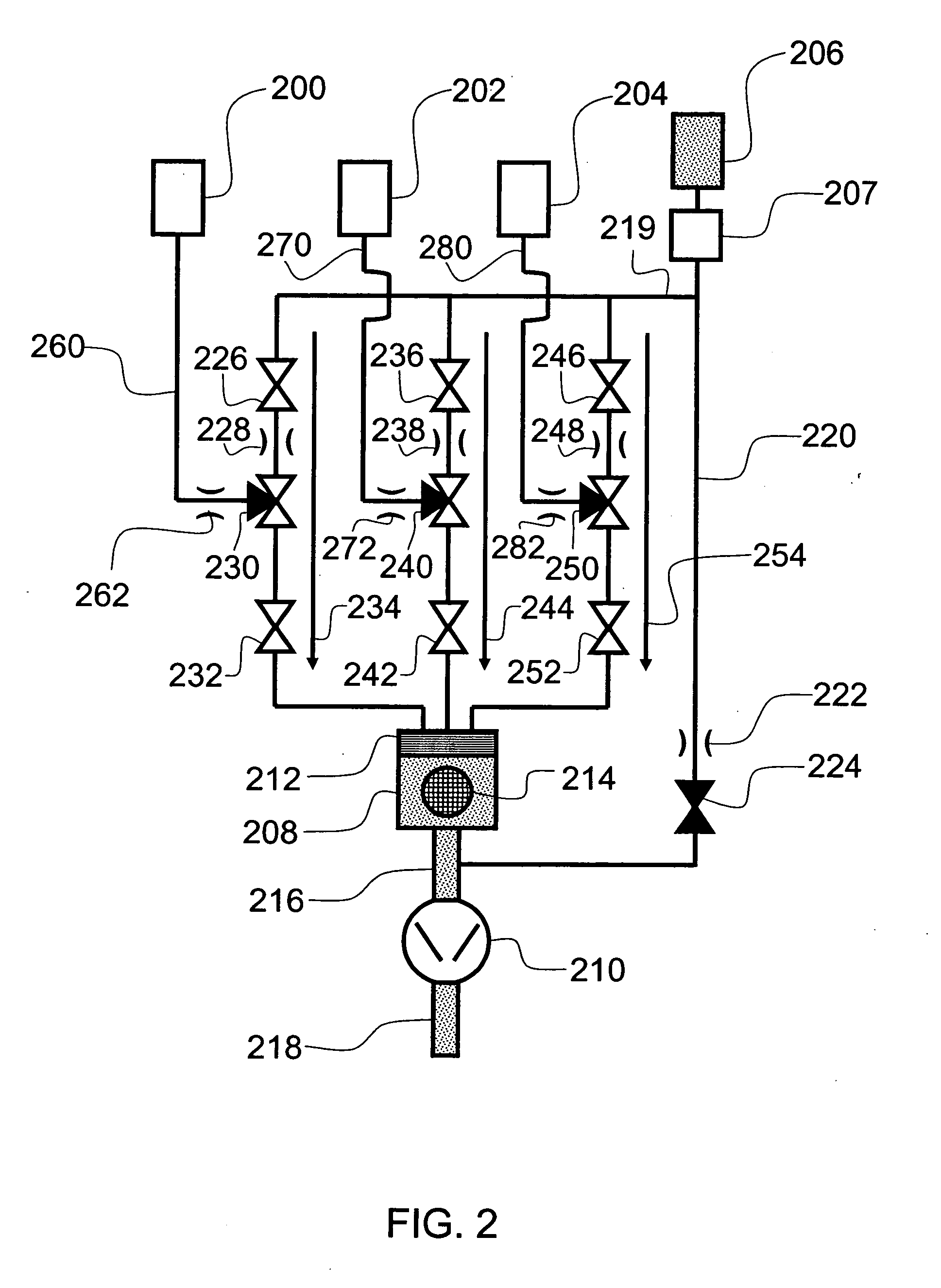
[0028] The gas dosing systems and methods described herein are preferably used for atomic layer deposition (ALD) processes and are typically utilized in an ALD reactor. As a result, the gas dosing systems and methods presented herein are described in the context of atomic layer deposition (ALD) processes. However, one of skill in the art will recognize that they can be utilized in the provision of reactants in other deposition processes. In addition, while not separately illustrated, the skilled artisan will readily appreciate that the flow sequences described herein can be controlled by a computer through software programming and / or hardwiring arranged to open and close gas control valves in the desired sequence.

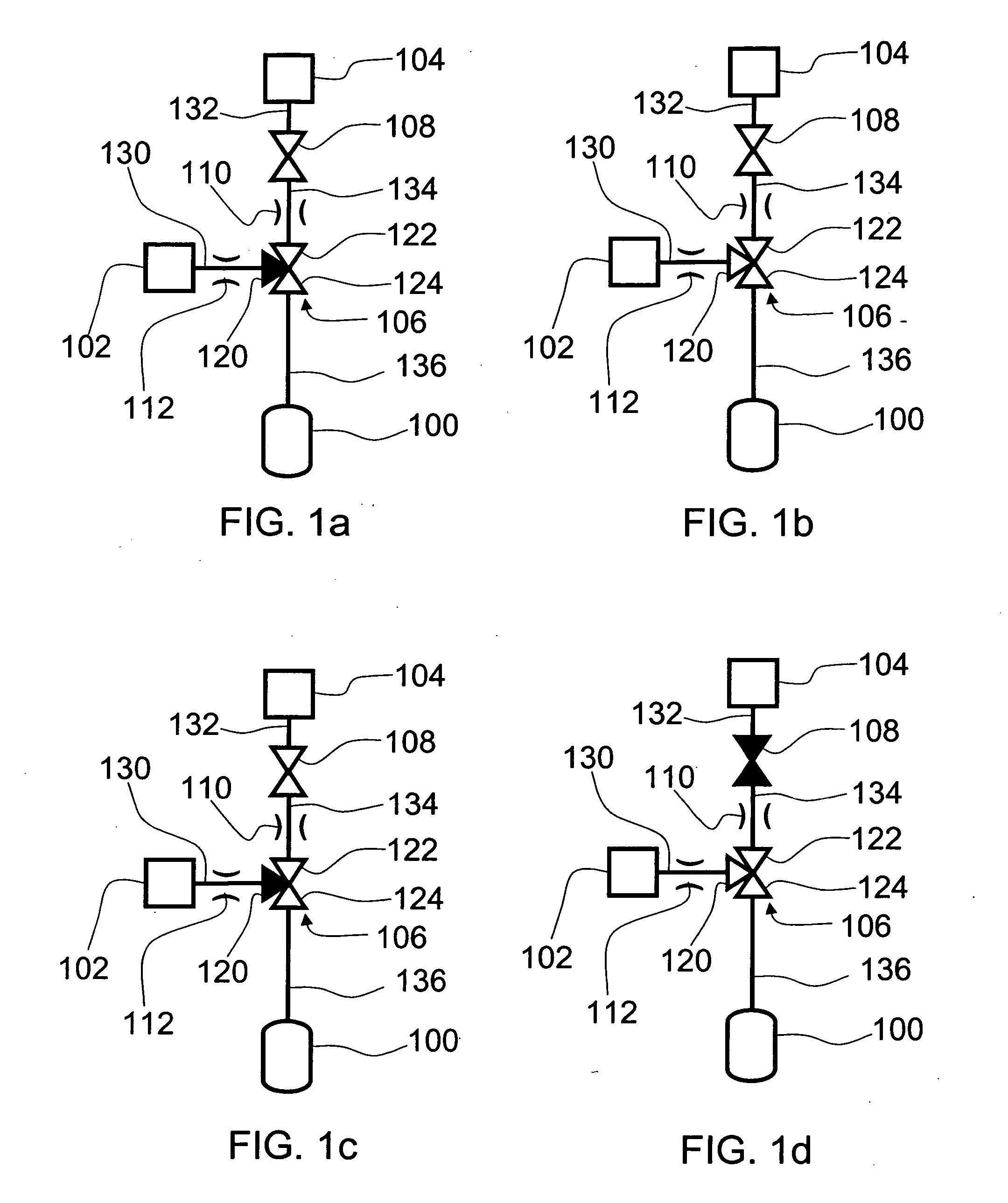
[0029] The gas dosing systems described herein typically comprise a reactant supply source, a gas flow control valve and at least one pre-calibrated orifice that acts as a choked-flow element. While described with the use of a pre-calibrated orifice, one of skill in the ar...


PUM

PropertyMeasurementUnit
pressure ratio P2/P1aaaaaaaaaa
vapor pressureaaaaaaaaaa
temperatureaaaaaaaaaa

Abstract

A source system for introducing gaseous source chemicals to a reaction space is provided. The source system comprises an inactive gas source, a pressure controller, a reactant supply source, a gas flow control valve and a choked-flow element.

Description

REFERENCE TO RELATED APPLICATION [0001] The present application claims the priority benefit under 35 U.S.C. §119(e) to U.S. Provisional Application No. 60 / 538,019, filed Jan. 20, 2004.FIELD OF THE INVENTION [0002] The present invention relates generally to a semiconductor processing apparatus and more particularly, a vapor reactant source system for a semiconductor processing apparatus, such as for depositing thin films on a substrate surface. BACKGROUND OF THE INVENTION [0003] Thin films may be grown on the surface of substrates by several different methods. These methods include vacuum evaporation deposition, Molecular Beam Epitaxy (MBE), different variants of chemical vapor deposition (CVD) including low-pressure and organometallic CVD and plasma-enhanced CVD, and atomic layer epitaxy (ALE), which has been more recently referred to as atomic layer deposition (ALD) for the deposition of a variety of materials. [0004] Orifices are used as gas flow restrictors, for example in CVD pr...

Claims


Application Information

Patent Timeline
Patent Type & Authority Applications(United States)
IPC IPC(8): C23C16/00
CPCC23C16/45525C23C16/45544
Inventor KILPELA, OLLI V.KOSTAMO, JUHANA
Owner ASM INTERNATIONAL
Why Eureka
Try Eureka