Apparatus and method for hyperthermia treatment
a technology applied in the field of apparatus and treatment method for hyperthermia, can solve the problem of more difficult depth-directed treatmen
- Summary
- Abstract
- Description
- Claims
- Application Information
AI Technical Summary
Benefits of technology
Problems solved by technology
Method used
Image
Examples
first embodiment
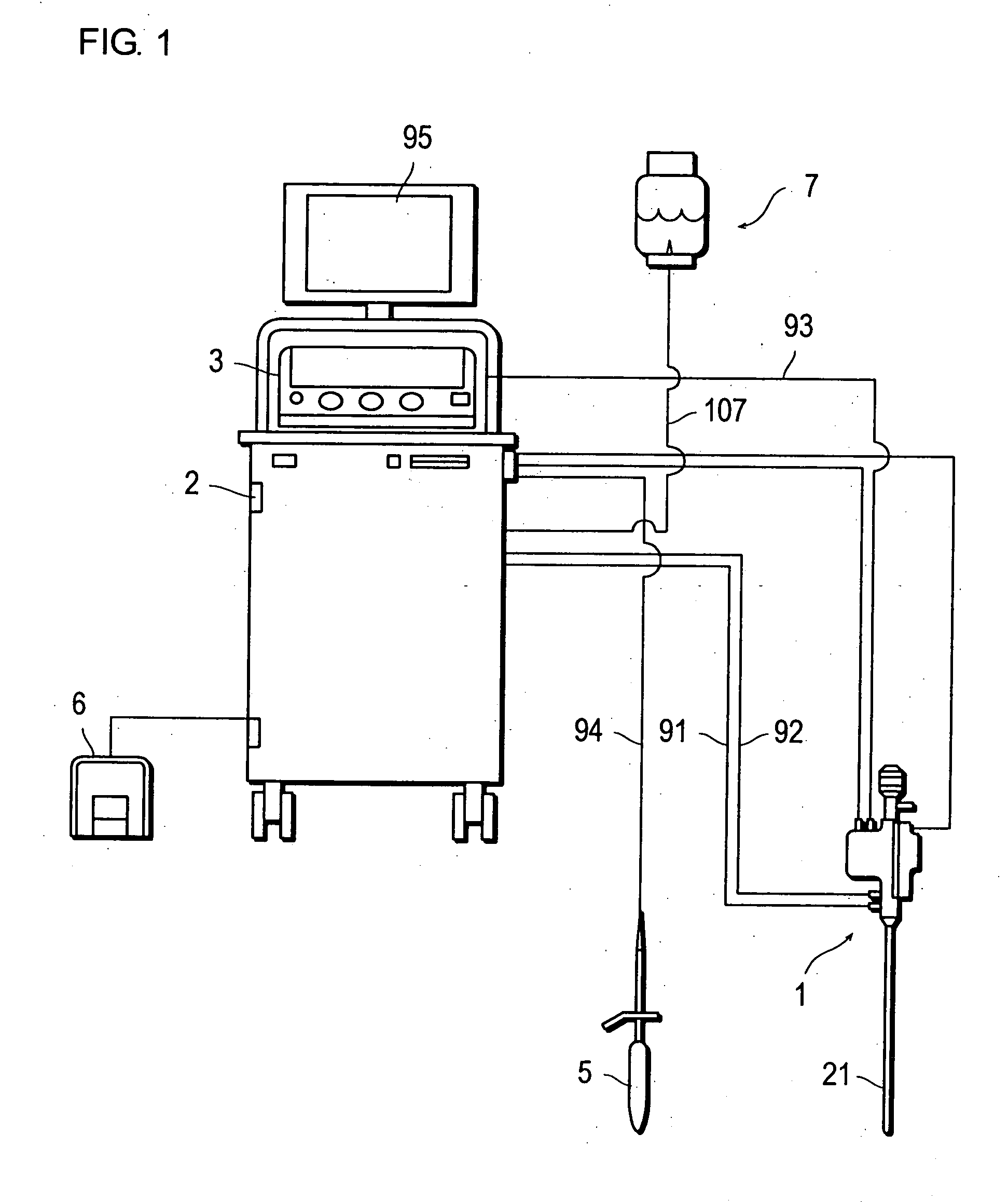
[0038]FIG. 1 shows the constitution of an apparatus for hyperthermia treatment according to an embodiment of the present invention.
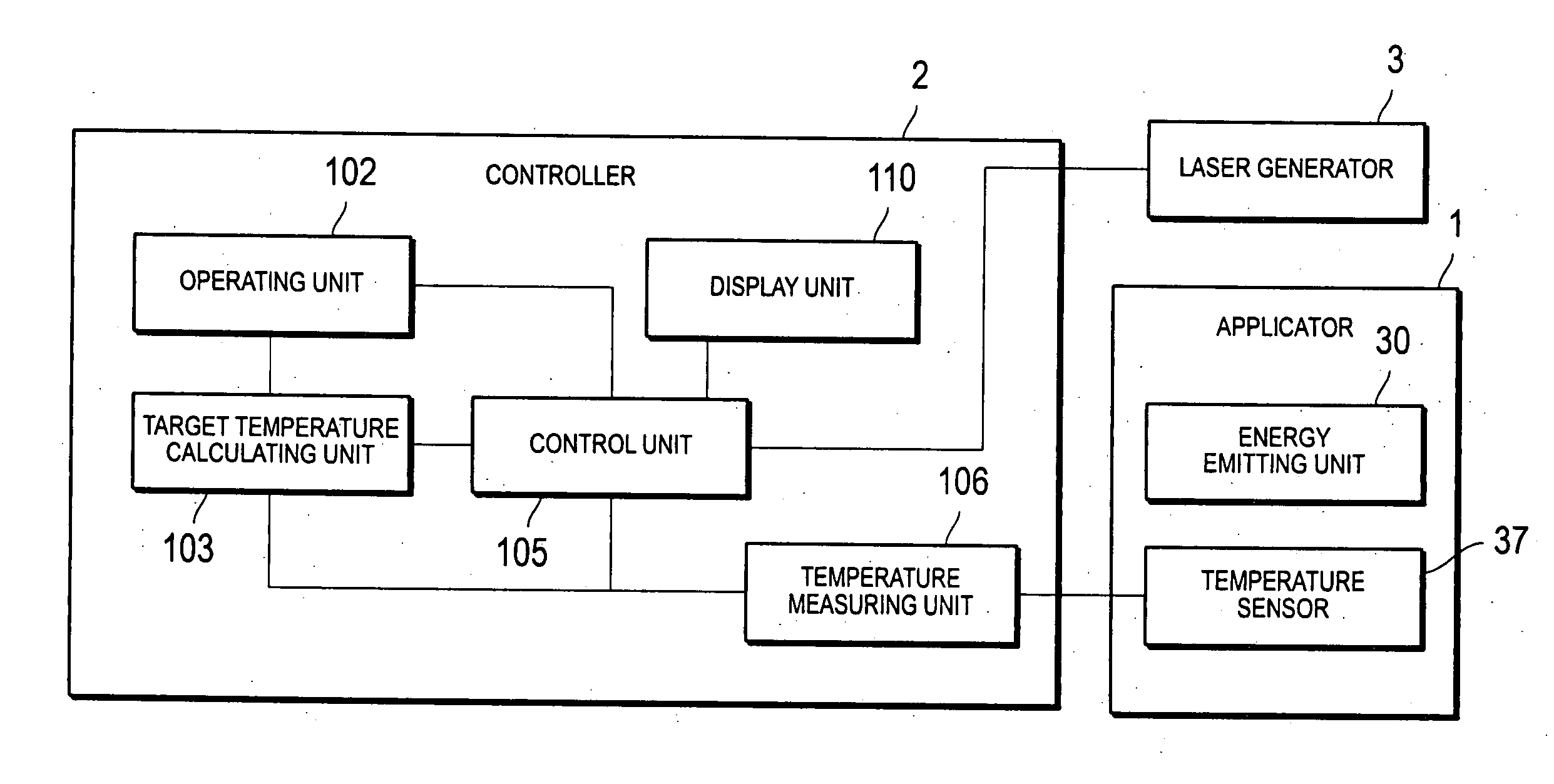
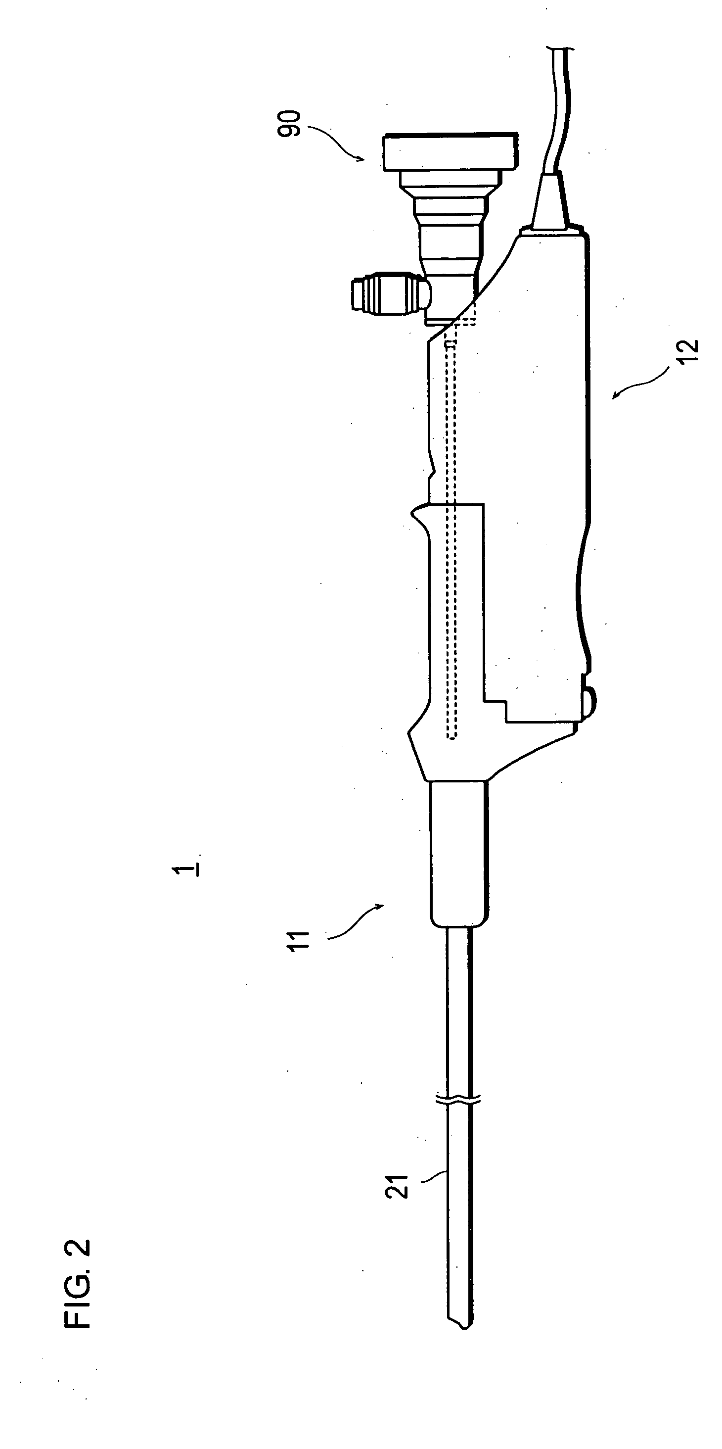
[0039] The apparatus for hyperthermia treatment has an applicator 1, a controller 2, a laser generator 3, a rectal probe 5, a foot switch 6, and a cooling water refilling tank 7.
[0040] The applicator 1, the laser generator 3, the rectal probe 5, the foot switch 6, and the cooling water refilling tank 7 are all connected to the controller 2.
[0041] A cooling device (not shown) for supplying cooling water as cooling fluid to the applicator 1 is provided inside the controller 2. The controller consists of a cooling water pack for holding an approximately constant amount of cooling water, a pump (fluid feeder) for circulating the cooling water, and a Peltier effect unit for maintaining the cooling water at a predetermined temperature. The cooling water pack cools the water temperature to a fixed temperature by being pressed against the Peltier effect unit....
second embodiment
[0135] The second embodiment is to modify the period setting of the constant power period in the first embodiment from ending the period by a set time to ending the period when the temperature change turns upward. Other elements of the constitution such as the structure of the apparatus and process sequence other than the constant power period remain the same as in the first embodiment.
[0136]FIG. 13 is a flow chart showing the temperature control process sequence of the second embodiment. Since the processes other than those described bellow are identical to those processes for temperature control already described in the first embodiment, their descriptions are not repeated here.
[0137] The control unit 105 instructs the laser generator 3 to maintain a predetermined constant power value when the treatment is started (S41). The power value at this time is, for example, 5 W.
[0138] Next, the control unit 105 instructs the temperature measuring unit 106 to measure the current tempera...
third embodiment
[0142] The third embodiment is different from the first and second embodiments in that the temperature rise curve in the temperature rise period is defined by a plurality of mathematical formulas.
[0143] Therefore, the third embodiment is different from the first and second embodiments only in the formulas that are used in calculating the temperature rise curve in the step S3 and the rest of the embodiment including the constitution of the apparatus and the process sequence is identical to those of the other emobodiments. Therefore, the descriptions of those similar features are not repeated here.
[0144]FIG. 14 is a graph showing the target temperature change pattern in the third embodiment.
[0145] As can be seen from the drawing, the temperature rise curve of the temperature rise period is expressed by two line segments, zone-a and zone-b, in the third embodiment.
[0146] Therefore, the formulas for this period are:
in zone-a, temperature T—a=a×time+initial temperature (3)
in zone-...
PUM
 Abstract
Description
Claims
Application Information
 - R&D
- Intellectual Property
- Life Sciences
- Materials
- Tech Scout
- Unparalleled Data Quality
- Higher Quality Content
- 60% Fewer Hallucinations
Browse by: Latest US Patents, China's latest patents, Technical Efficacy Thesaurus, Application Domain, Technology Topic, Popular Technical Reports.
© 2025 PatSnap. All rights reserved.Legal|Privacy policy|Modern Slavery Act Transparency Statement|Sitemap|About US| Contact US: help@patsnap.com


