
Method for optimizing groove structure of friction plate of wet type friction engagement apparatus

Inactive Publication Date: 2005-10-13
DAINATSUKUSU
View PDF1 Cites 31 Cited by
  • Summary
  • Abstract
  • Description
  • Claims
  • Application Information

AI Technical Summary

Benefits of technology

[0009] The object of the present invention is to provide an optimizing method for a groove structure of a wet-type friction engaging element, which can reduce drag torque by increasing outgoing flow of lubricating oil on the friction surface, and by increasing the content of air in the lubricating oil.

Problems solved by technology

Such torque is called a drag torque, and this may cause a loss of motive power in an automatic transmission.

Method used


Image

  • Method for optimizing groove structure of friction plate of wet type friction engagement apparatus
  • Method for optimizing groove structure of friction plate of wet type friction engagement apparatus
  • Method for optimizing groove structure of friction plate of wet type friction engagement apparatus

Examples


example)

(EXAMPLE)

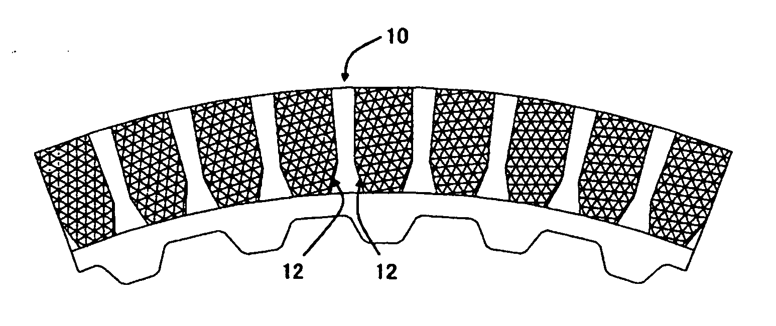
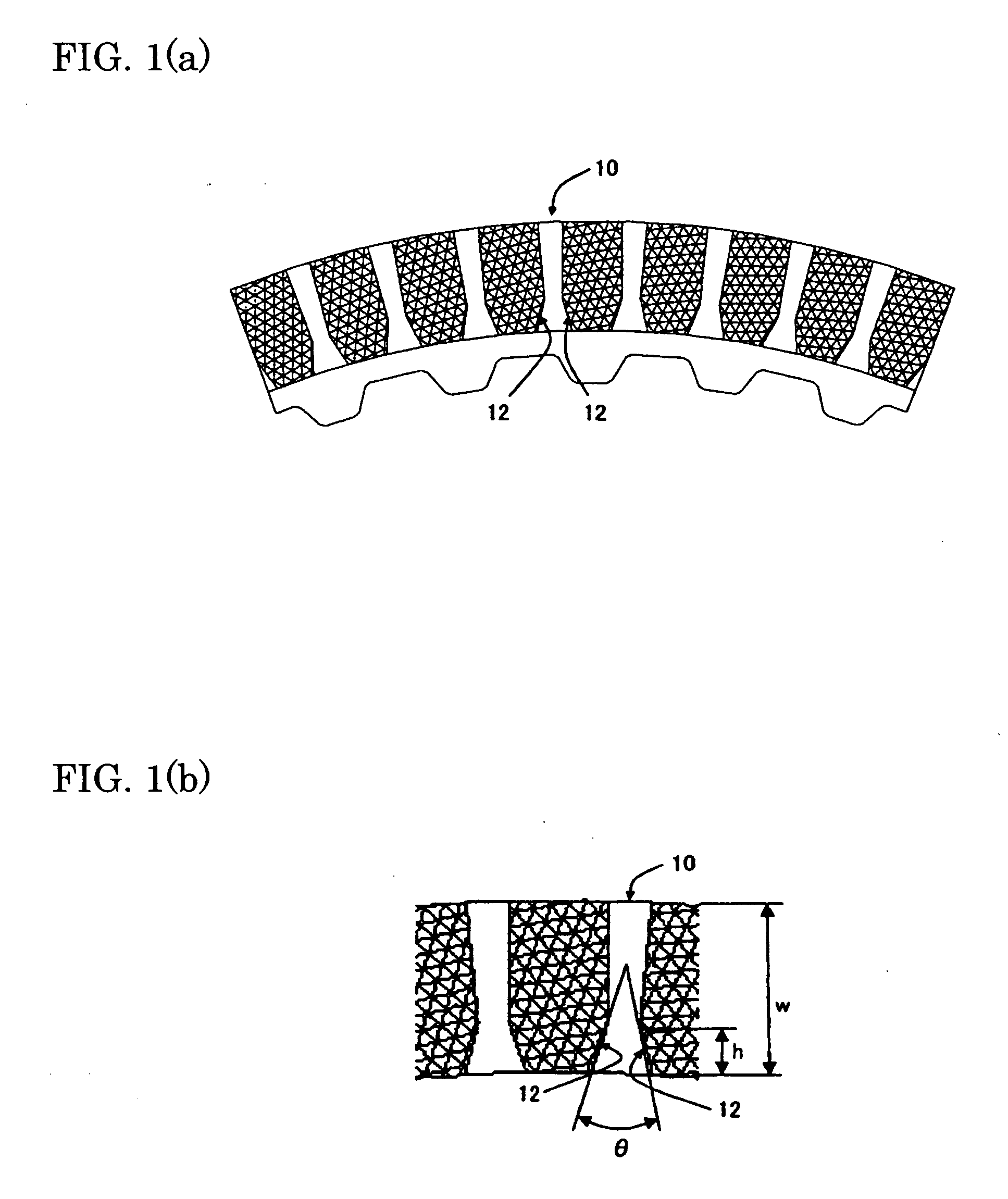
[0044] An example of the present invention is a friction disk with inner diameter of 140 mm and outer diameter of 160 mm, wherein an inner section of the groove widens inwardly of the friction disk, and the groove is formed with the entrance angle (opening angle) θ of 30 degrees and the ratio h / w of the full length w of the groove to the length h of the inner section of 0.3, using the optimizing method according to the present invention.


PUM


Abstract

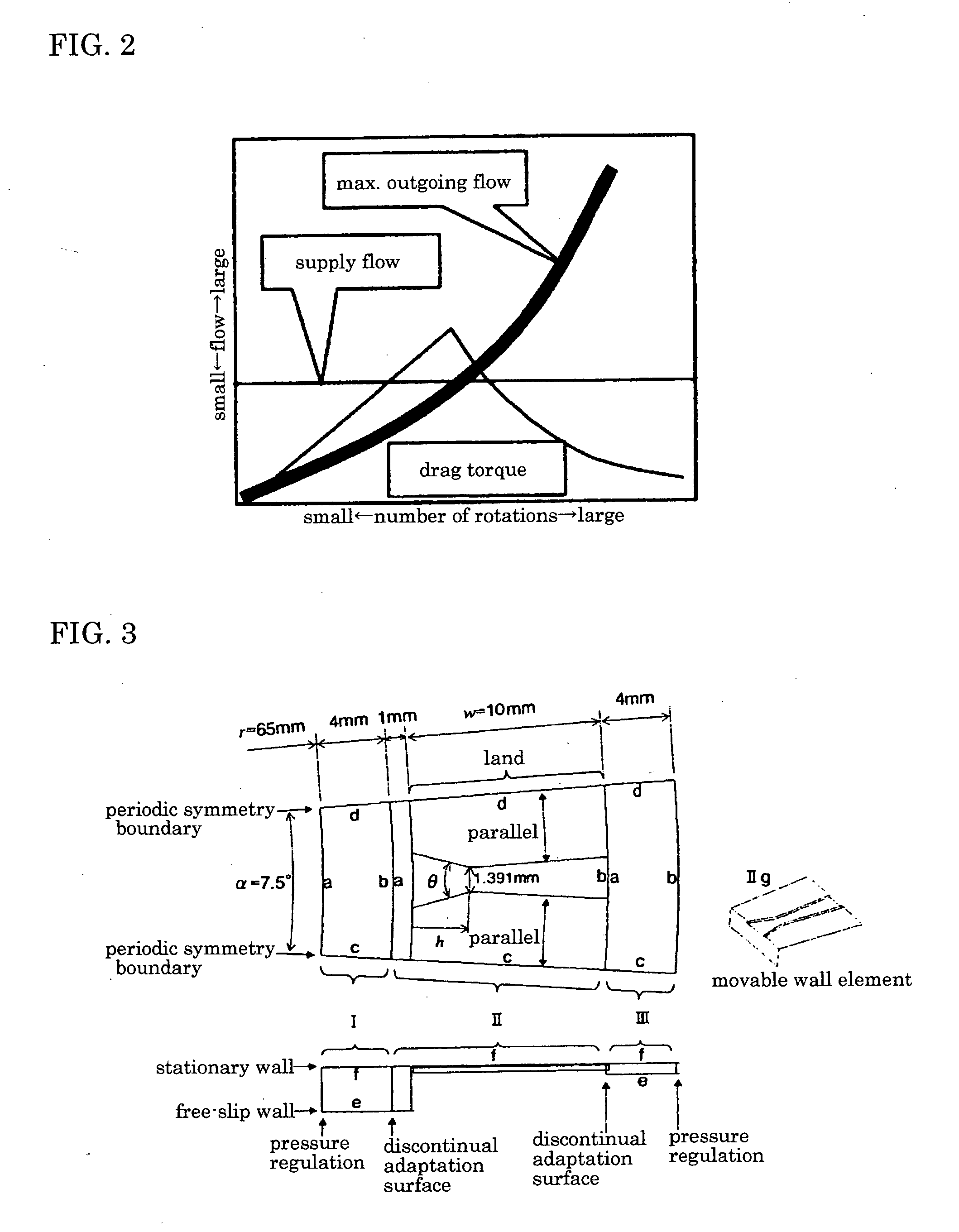
The object of the present invention is to provide an optimizing method for a groove structure of a friction disk of a wet-type friction engaging element, which can reduce drag torque by increasing outgoing flow of lubricating oil on the friction surface and increasing the content of air in the lubricating oil. The optimizing method for a groove structure of a friction disk of a wet-type friction engagement element comprising a sectoral inner section 12 of a groove 10 widening inwardly formed on the surface of a friction member of the wet-type friction engaging element, wherein the outgoing flow per groove area is calculated based on the entrance angle (opening angle) θ of the inner section 12 and the ratio h / w of the full length w of the groove 10 to the length h of the inner section; and then a range of the entrance angle (opening angle) θ of the inner section and the ratio h / w of the full length w of the groove to the length h of the inner section is determined where the outgoing flow per groove area is at least a certain value.

Description

TECHNICAL FIELD OF THE INVENTION [0001] The present invention belongs to the technical field of a groove structure of a clutch of a wet-type friction engagement apparatus or a wet-type friction brake etc., used in a transmission for motor vehicles or in a transmission for industrial or construction machines. BACKGROUND ART [0002] Conventionally, a wet-type friction engaging element has been used for example in an automatic transmission for motor vehicles. [0003] As the wet-type friction engaging element of the automatic transmission, there have been used a friction plate, a brake band, etc. in a multiple disk friction engagement apparatus. As shown in FIG. 10, a multiple disk friction engagement apparatus 20 conventionally comprises a hydraulic-actuated piston 21, and a plurality of wet-type friction plates 22 and mating plates 23 arranged alternately so as to be engaged with each other by the piston 21. [0004] The wet-type friction disk 22 comprises a core plate 24 and friction mem...

Claims


Application Information

Patent Timeline
IPC IPC(8): F16D13/64F16D13/74F16D65/12F16D69/00
CPCF16D13/64F16D13/74F16D65/12F16D2069/004F16D13/648F16D25/0638F16D25/123
Inventor LI, CHEN YUTAKAHASHI, JIN
Owner DAINATSUKUSU
Learn More