Device and method for eye problems

a technology for eye problems and devices, applied in the field of devices and methods for improving vision, can solve problems such as numerous physical injuries, decreased night vision, and inability to see dimly lit places such as movie theaters

Inactive Publication Date: 2005-10-13
TK & CORP
View PDF6 Cites 1 Cited by
  • Summary
  • Abstract
  • Description
  • Claims
  • Application Information

AI Technical Summary

Benefits of technology

[0011] The device described above can be converted into a portable version which comprises a frame configured to be worn by a user, a liquid crystal display fitted in the frame, an infrared illuminator mounted to the frame, and a micro-camera mounted to the frame. The infrared illuminator is operative to illuminate an infrared light on a predetermined area in front of the user. The micro-camera is operative to capture an image of the predetermined area and compress the image. The device further comprises a wavelength shifter to convert the processed image with infrared wavelength to an image with visible wavelength. A lenticular may be incorporated adjacent to the liquid crystal display to provide three-dimensional visual effect.

Problems solved by technology

When the rod cells start degenerating, a decrease in night vision and the inability to see dimly lit places such as movie theaters take places.
Such gradual reduction in the ability to see peripherally may cause numerous physical problems such as tripping over objects or a motor vehicle accidents.

Method used


Image

  • Device and method for eye problems
  • Device and method for eye problems
  • Device and method for eye problems

Examples


Embodiment Construction

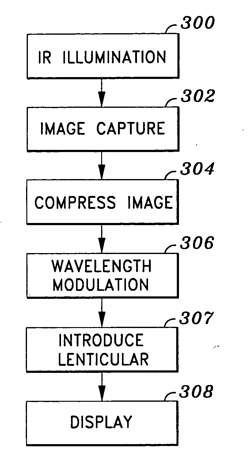
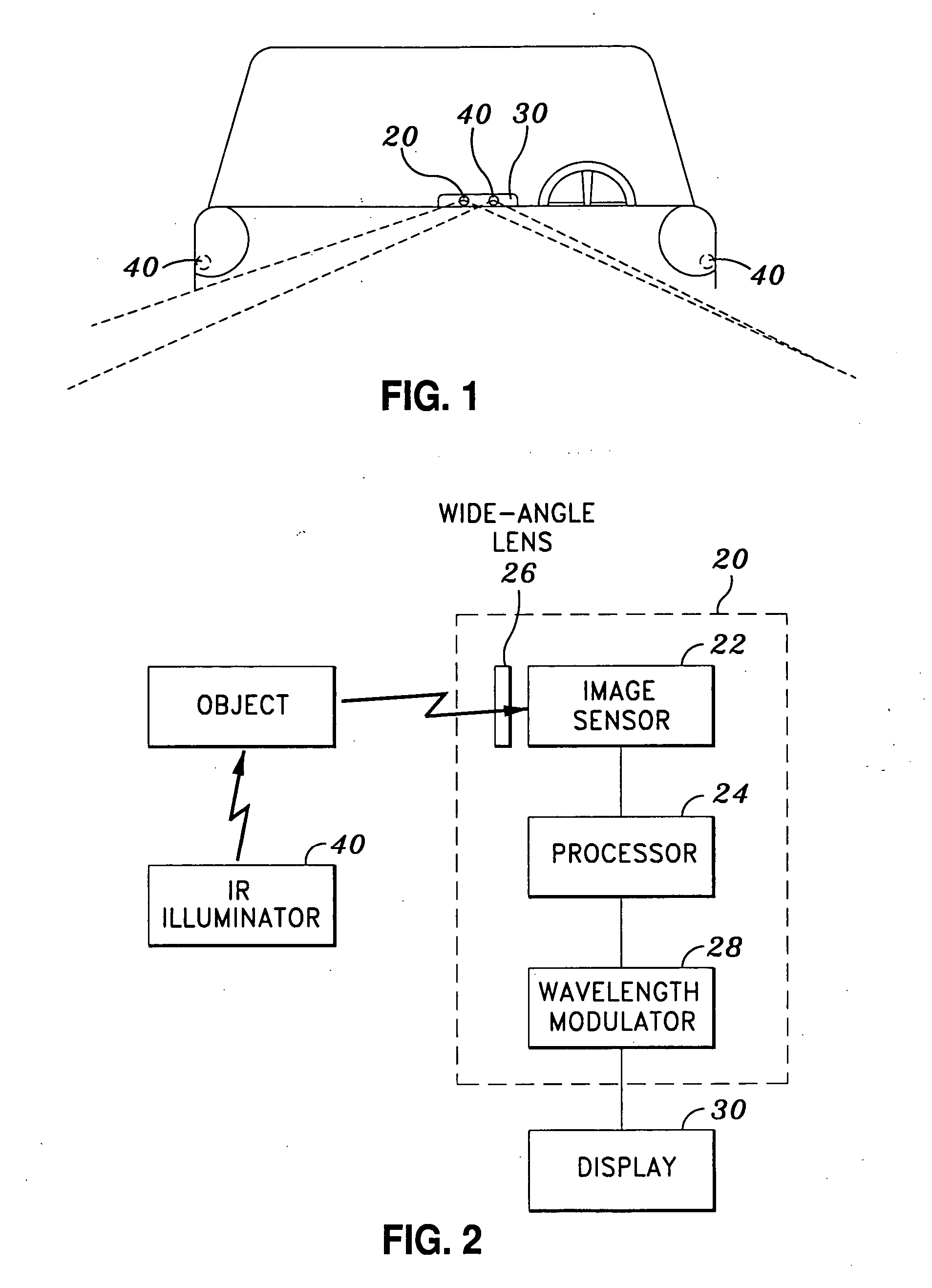
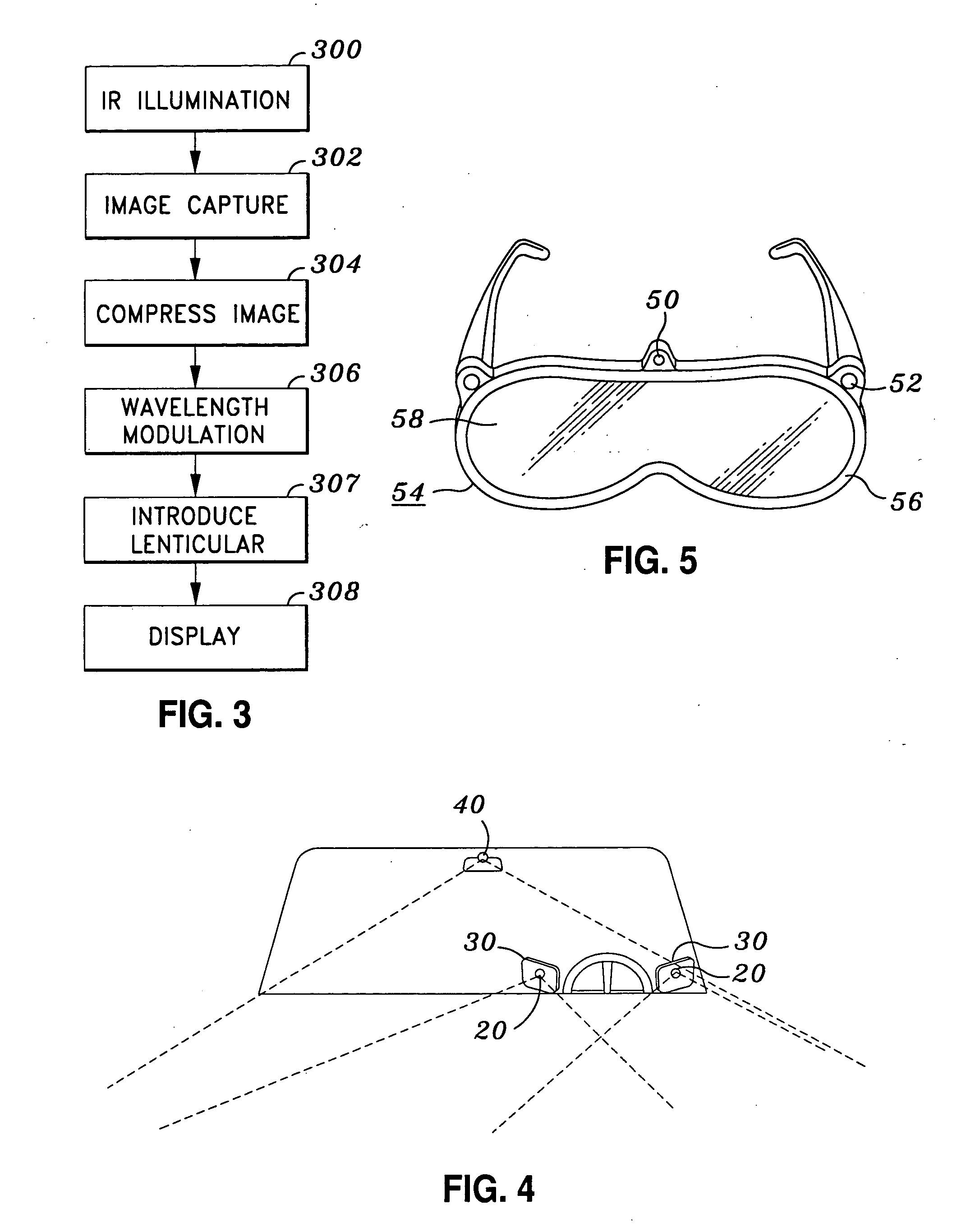
[0018] Referring now to the drawings wherein the showings are for purpose of illustrating preferred embodiments of the present invention only, and not for purposes of limiting the same. As shown in FIGS. 1 and 2, the present invention provides a vision improvement device which incorporates a camera 20 and a display 30 in electric communication with each other. The camera 20 is preferably installed in a vehicle 10 at a position operative to capture a wide angle of view in front of the driver without obstructing the view of the driver. To obtain a wide angle and unobstructed of view, the camera 20 may also be mounted to the vehicle 10 externally. The display 30 is either installed above or built in the dashboard 12 of the vehicle 10, such that the driver can glance at the display 30 without being distracted by moving his or her head.

[0019] The camera 20 includes an image capturing device 22 for scanning a predetermined area and capturing an image of the predetermined area in front of...


PUM


Abstract

A device for improving vision of a person, having a camera and a display. The camera has an image sensor operative to capture an image of a predetermined area in front of the person, and an image processor operative to compress the image. The display is operative to reproduce the compressed image. Preferably, the image sensor is effective to detect infrared light, and an infrared illuminator is incorporated to radiate an infrared light upon the predetermined area. Therefore, even in the dim-lit condition, the predetermined area can be properly imaged. However, as the infrared image is barely visible to human eyes, a wavelength shifter is used to translate the compressed image with infrared wavelength to visible wavelength before the compressed image is displayed by the display.

Description

CROSS-REFERENCE TO RELATED APPLICATIONS [0001] Not Applicable STATEMENT RE: FEDERALLY SPONSORED RESEARCH / DEVELOPMENT [0002] Not Applicable BACKGROUND OF THE INVENTION [0003] The present invention relates in general to a device and a method for vision improvement, and more particularly, to a device and a method which improve night vision and peripheral vision of a driver who has vision deficiencies such as retinitis pigmentosa (RP). [0004] There are two types of photoreceptors in the retina, including rod cells and cone cells. The cone cells are concentrated in the macula (center of the retina) to perceive color and fine visual detail at the center of vision. The rod cells are present both within and outside the macula and are responsible for night vision, seeing in dim light and side or peripheral vision. As the peripheral retina is predominated with rod cells, the peripheral retina is thus responsible for side vision and vision in low light conditions. When the rod cells start dege...

Claims


Application Information

Patent Timeline
Patent Type & Authority Applications(United States)
IPC IPC(8): H01L31/00B60R1/00
CPCB60R1/00B60R2300/103B60R2300/105B60R2300/106B60R2300/107B60R2300/30B60R2300/8053
Inventor WING, THOMAS W.
Owner TK & CORP
Why Eureka
Try Eureka