Rear feed micro-fluidic two-way isolation valve

a micro-fluidic and two-way isolation technology, applied in the field of valves, can solve the problems of inefficiency of xyz machines coming from the bottom of the cuvette, takes approximately 2-3 seconds to press the end cap into the housing, etc., and achieves the effect of short movement of the plunger rod, reducing power consumption of the valve, and quick operation tim

Inactive Publication Date: 2005-10-13
KLOEHN
View PDF16 Cites 5 Cited by
  • Summary
  • Abstract
  • Description
  • Claims
  • Application Information

AI Technical Summary

Benefits of technology

[0008] The present invention, in a preferred embodiment, is particularly but not exclusively, useful as a rear feed micro-mini solenoid-operated valve for positioning mechanisms and has the ability to control and adjust the flow amount, dispense volume and dispense speed. The novel design of the valve provides a quick operating time and full flow with relatively short movement of the plunger rod. This allows for reduced power consumption by the valve and reduces unnecessary use. In one aspect, a solenoid-operated valve comprises external elements that include a coil housing that defines an axis therethrough and an end cap having a sealing apex on a first side and coupled to a needle on a second side.

Problems solved by technology

Pressing the end cap into the housing, however, takes approximately 2-3 seconds.
Having an XYZ machine come from the bottom of the cuvettes would be inefficient because of the wiring of the XYZ machine.

Method used


Image

  • Rear feed micro-fluidic two-way isolation valve
  • Rear feed micro-fluidic two-way isolation valve
  • Rear feed micro-fluidic two-way isolation valve

Examples


Embodiment Construction

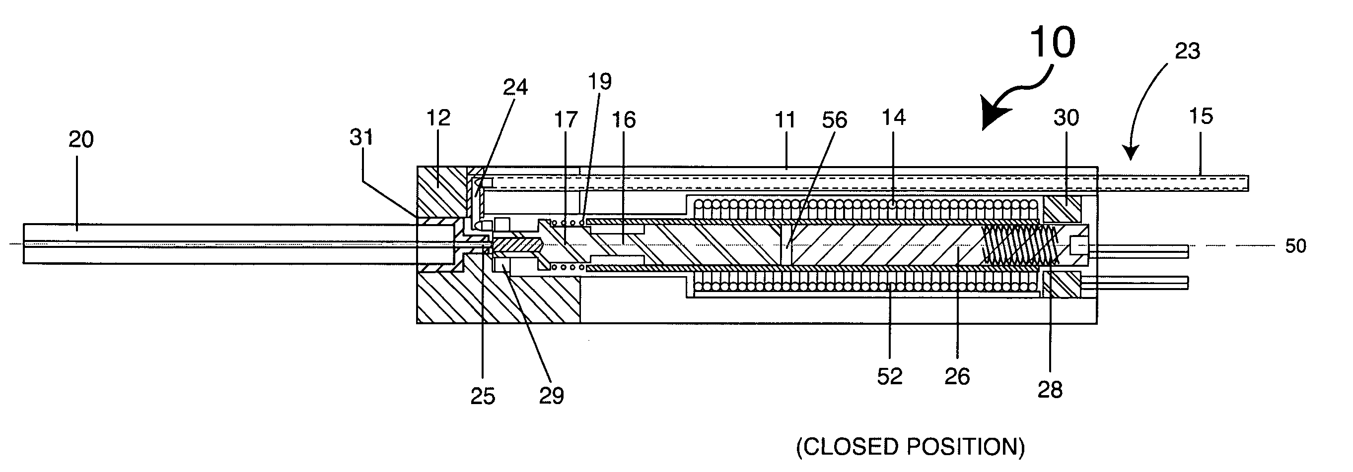
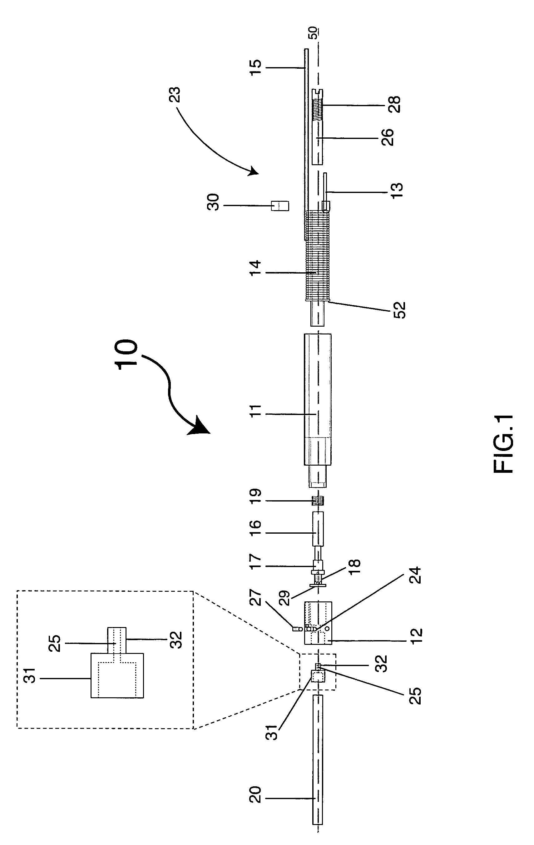
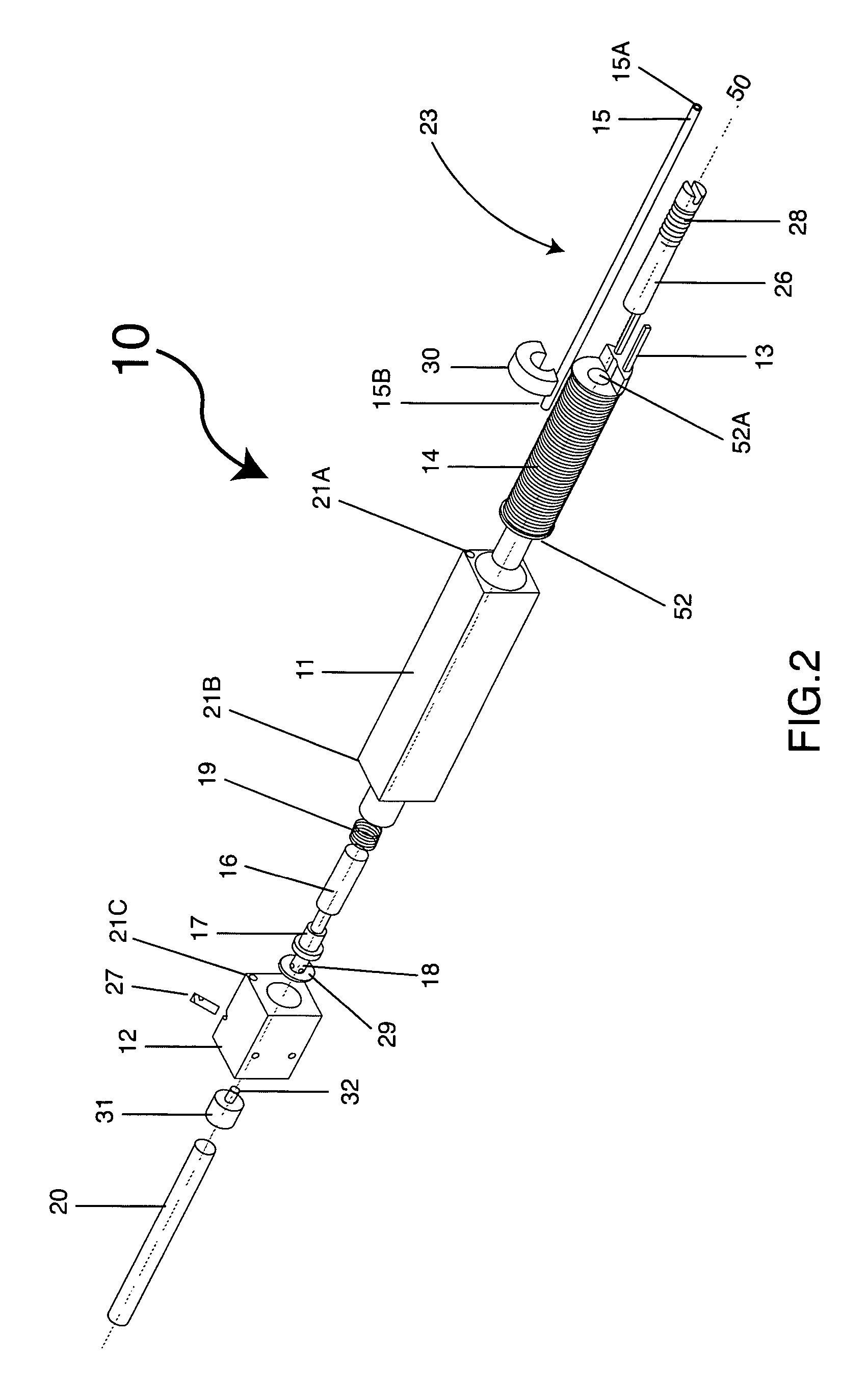
[0036] Referring initially to FIG. 1, a first preferred embodiment of a solenoid-operated valve 10 according to the present invention is shown. The valve 10 is a two-way isolation valve in that the valve 10 has two positions: open and closed. In this example, the valve 10 is de-energized in the closed position. The valve 10 comprises external components including a coil housing 11 and an end cap 12. A top or rear end 23 of the solenoid valve 10 includes electrical leads 13 that provide power to energize a solenoid coil 14. The valve 10 includes an inlet 15 at the rear end 23 of the valve 10 and an outlet 20 on the bottom, in order to conveniently couple the valve 10 to a positioning mechanism, such as an XYZ machine (not shown). In a preferred embodiment, the valve 10 is an isolated valve that is fed through the top or rear end 23.

[0037] Unlike conventional valves, the housing 11 is square with four 0.250 inch sides, allowing many valves to be utilized in close proximity so as to p...


PUM


Abstract

A rear feed solenoid-operated valve design is particularly suited for micro-fluidic applications. The solenoid valve contains various structures and features that provide for small dispense volumes, small internal volume, and fast operating speed. The valve includes an inlet, outlet, coil housing, magnetic plunger rod and a diaphragm assembly. In a preferred embodiment, the diaphragm assembly ensures zero leakage. The solenoid-operated valve further has features allowing for low power consumption. The valve is placed at a desired location by a positioning mechanism located at the rear end of the valve. The positioning mechanism feeds fluid through the inlet and dispenses the fluid at the outlet located at the front, or bottom of the valve.

Description

[0001] PRIORITY CLAIM [0002] This application relates to U.S. Provisional Patent Application Ser. No. 60 / 561,777 filed on Apr. 12, 2004 which is incorporated herein by reference and to which priority is claimed pursuant to 35 USC §119.BACKGROUND OF THE INVENTION [0003] 1. Field of the Invention [0004] The present invention pertains generally to valves for physical transport and isolation of liquids and gases. More particularly, the present invention pertains to fluidic dispense valves that are designed for low power and quick dispensing applications. [0005] 2. Description of the Prior Art and Related Information [0006] Solenoid-operated valves for isolation and transport of fluids are well known. An attractive characteristic of all solenoid-operated valves is that they can be remotely operated because electrical power is used to actuate the valve. Also, a solenoid valve is an attractive option when fluid systems require a valve to cycle open and closed, and thereby pass a set dispen...

Claims


Application Information

Patent Timeline
Patent Type & Authority Applications(United States)
IPC IPC(8): F16K31/06F16K99/00F16K31/02
CPCF16K31/0655F16K31/0672F16K99/0001F16K99/0015F16K99/0034F16K99/0046F16K2099/0084F16K2099/0086
Inventor KISH, WALTER J. JR.
Owner KLOEHN
Why Eureka
Try Eureka